Traceless midplane

a technology of traceless midplanes and tracing holes, which is applied in the direction of fixing connections, electrical apparatus construction details, and supporting structure mounting, etc., can solve the problems of increasing the difficulty of manufacturing backplanes and midplanes

Inactive Publication Date: 2003-03-25
JUMIPER NETWORKS INC
View PDF9 Cites 75 Cited by
  • Summary
  • Abstract
  • Description
  • Claims
  • Application Information

AI Technical Summary

Problems solved by technology

As the complexity of the network devices increases, the number of the traces in the backplanes and midplanes and the amount of pins and active circuitry required to manage the connections also

Method used


Image

  • Traceless midplane
  • Traceless midplane
  • Traceless midplane

Examples


Embodiment Construction

refers to the accompanying drawings. The same reference numbers in different drawings identify the same or similar elements. Also, the following detailed description does not limit the invention. Instead, the scope of the invention is defined by the appended claims and equivalents.

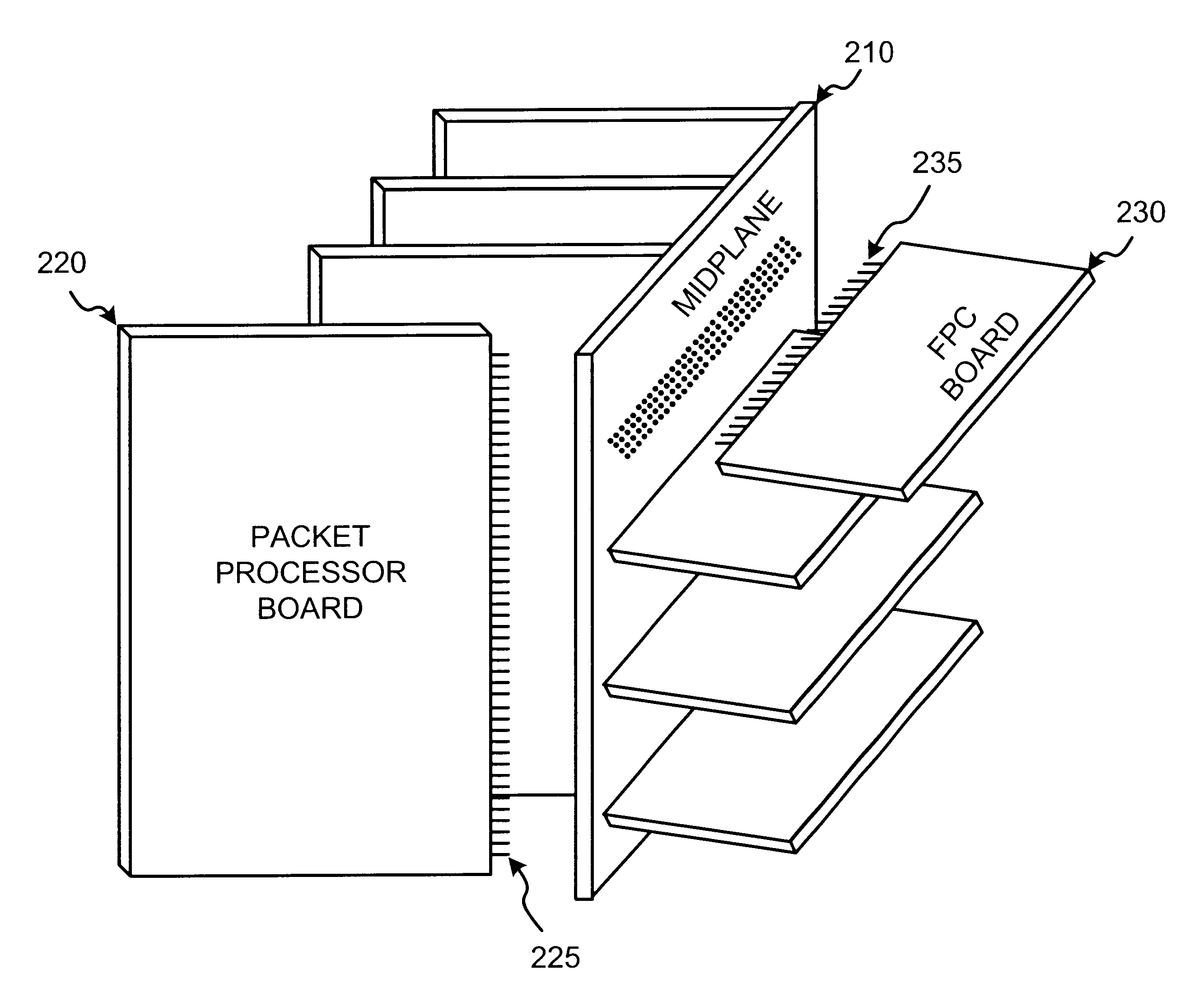
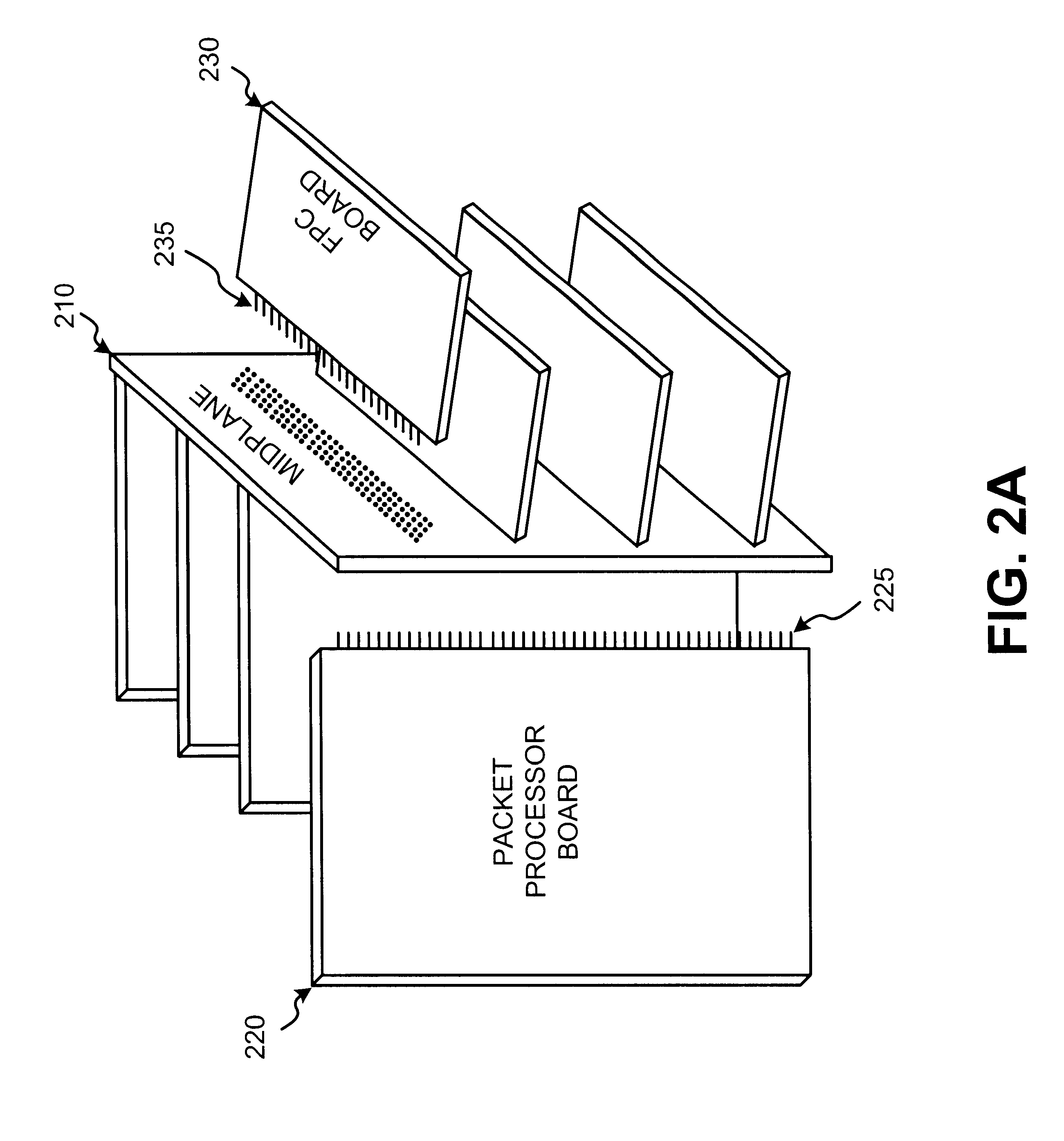
Systems and methods, consistent with the present invention, provide interconnectivity between boards of a network device via a midplane. The midplane contains no traces, pins, or active components, but instead contains conduits that provide direct electrical connections between pins of the interconnecting boards. Such a construction is easy to manufacture and minimizes electrical faults in the midplane and, therefore, minimizes the need to replace or troubleshoot the midplane.

EXEMPLARY NETWORK DEVICE CONFIGURATION

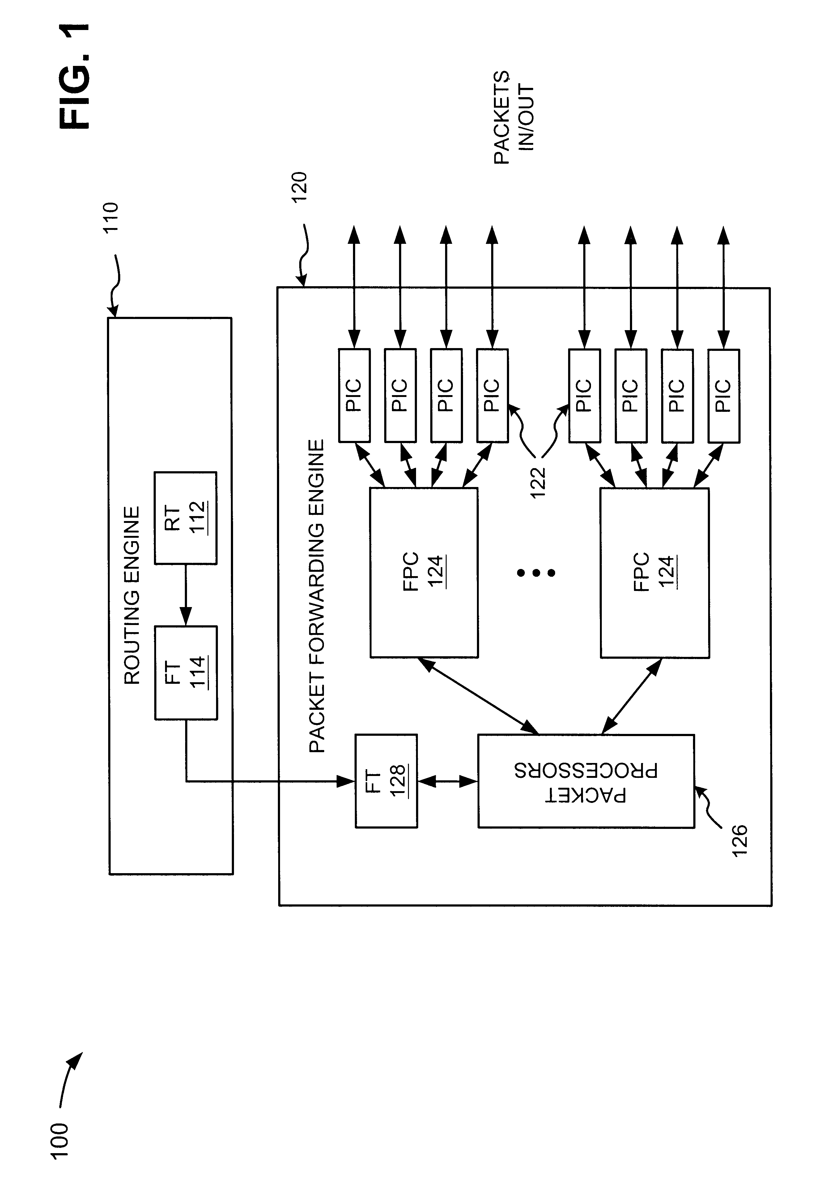
FIG. 1 is a diagram of an exemplary network device in which systems and methods consistent with the present invention may be implemented. In this particular implementation, the network device take...


PUM


Abstract

A traceless midplane contains substantially no traces, pins, or active components and includes a front portion and a back portion. The front portion includes first connectors. The back portion includes second connectors arranged in a grid pattern. Each of the second connectors includes electrically-conductive conduits that connect the second connector to a corresponding one of the first connectors through the midplane. The second connectors include data connection points, ground connection points, and clock connection points. At least some of the data connection points are separated from each other and from the clock connection points by the ground connection points.

Description

A. Field of the InventionThe present invention relates generally to routing systems and, more particularly, to a traceless midplane that interconnects multiple boards of a network device.B. Description of Related ArtConventional network devices include multiple processing and / or switching boards that communicate with one another. Often, a backplane or midplane interconnects these boards so that they can communicate. These backplanes and midplanes, however, typically include traces (i.e., internal or external wires that interconnect connection points on the backplanes or midplanes), connection pins, and / or active circuitry to facilitate the communication between the boards. As the complexity of the network devices increases, the number of the traces in the backplanes and midplanes and the amount of pins and active circuitry required to manage the connections also increase, making it increasingly difficult to manufacture the backplanes and midplanes.Also, a problem arises when an elec...

Claims


Application Information

Patent Timeline
IPC IPC(8): H05K7/14H05K1/14
CPCH01R12/58H01R12/523H05K7/1445H05K1/14
Inventor KRISHNAMURTHI, ASHOKANAND, RAMALINGAM K.
Owner JUMIPER NETWORKS INC
Why Eureka
Try Eureka