Three-dimensional window displaying apparatus and method thereof

a three-dimensional window and display apparatus technology, applied in the field of three-dimensional display apparatus, can solve the problems of difficult to observe the content of the hidden window, difficult to select a file in the hidden window,

Inactive Publication Date: 2003-04-01
FUJITSU LTD
View PDF12 Cites 109 Cited by
  • Summary
  • Abstract
  • Description
  • Claims
  • Application Information

AI Technical Summary

Benefits of technology

An object of the present invention is to provide a three-dimensional window displaying system that allows the user to observe an overlapped portion of windows from a different view point.
In particular, when the position of a view point from which windows and other objects are projected in a virtual three-dimensional space is determined, the windows and the other objects can be displayed as if the user observes them from a different view angle. Thus, the user can observe a particular window hidden behind other windows by changing his or her view point. Although the windows and other objects are three-dimensionally displayed, methods for processes corresponding to operations are not changed. Thus, operations that are performed in the conventional window system can be performed on three-dimensional windows.

Problems solved by technology

In the window system as shown in FIG. 1A, when many windows overlap with each other or a large window is displayed above another window, it is difficult to select a file in the hidden window.
In addition, it is difficult to observe the content of the hidden window.
Thus, when inclined windows overlap with each other, there are the same drawbacks as those with the system shown in FIG. 1A.

Method used


Image

  • Three-dimensional window displaying apparatus and method thereof
  • Three-dimensional window displaying apparatus and method thereof
  • Three-dimensional window displaying apparatus and method thereof

Examples


Embodiment Construction

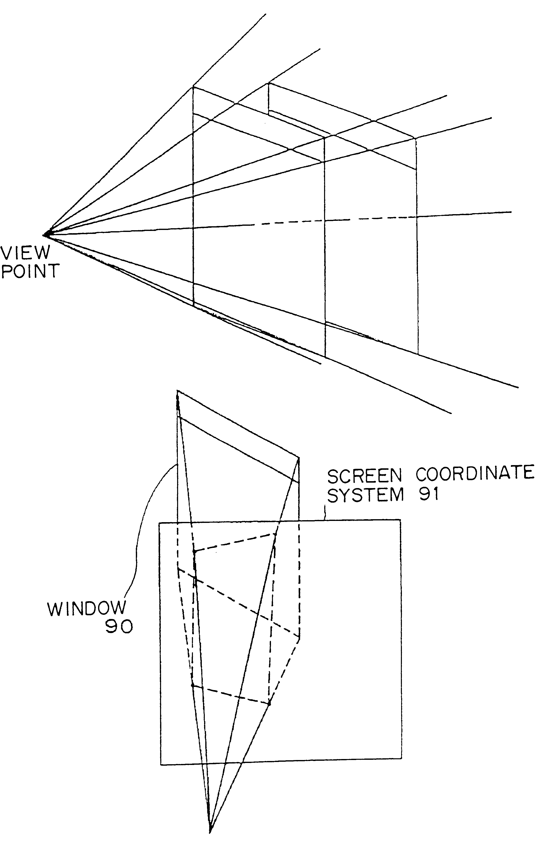
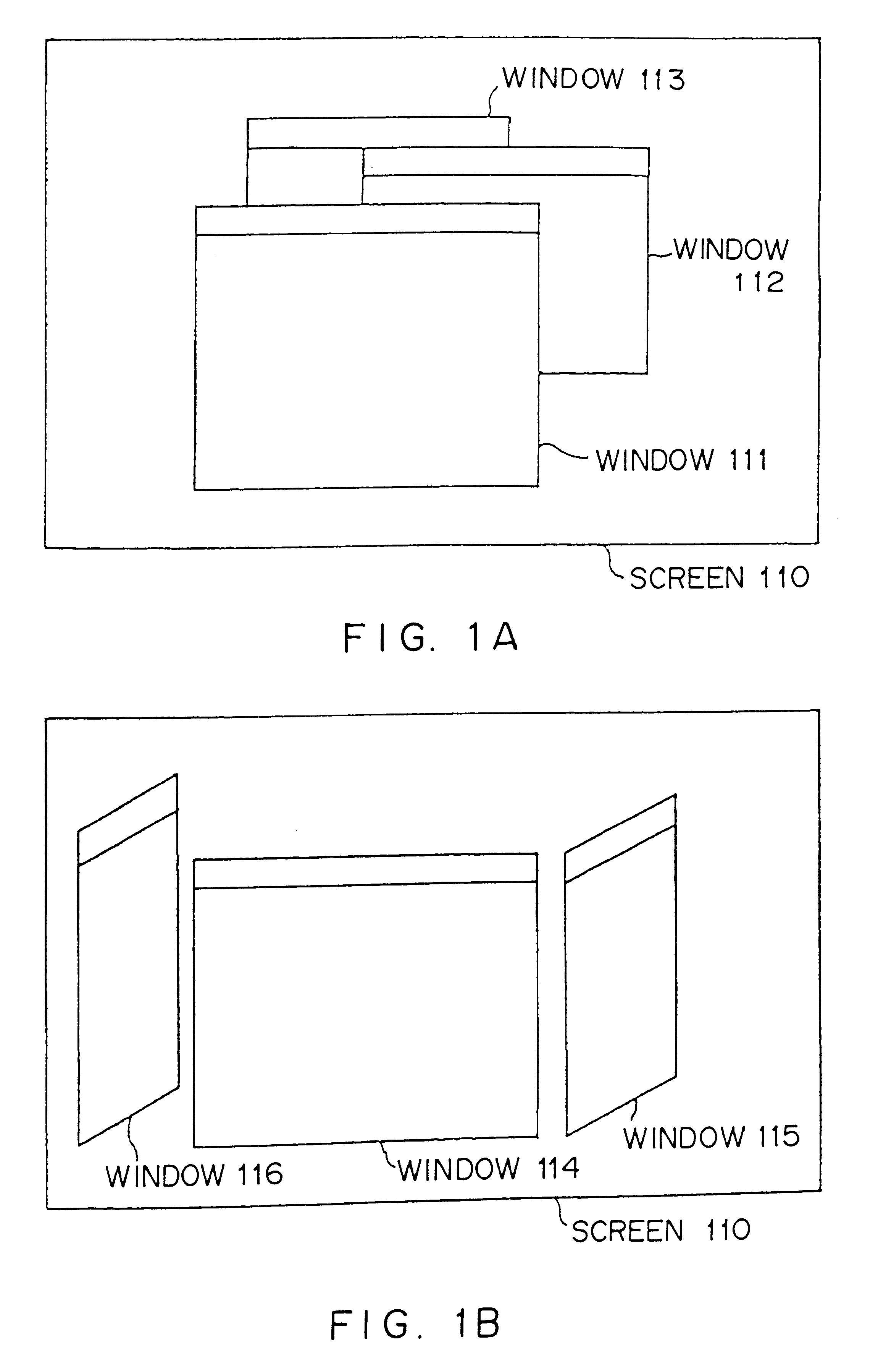
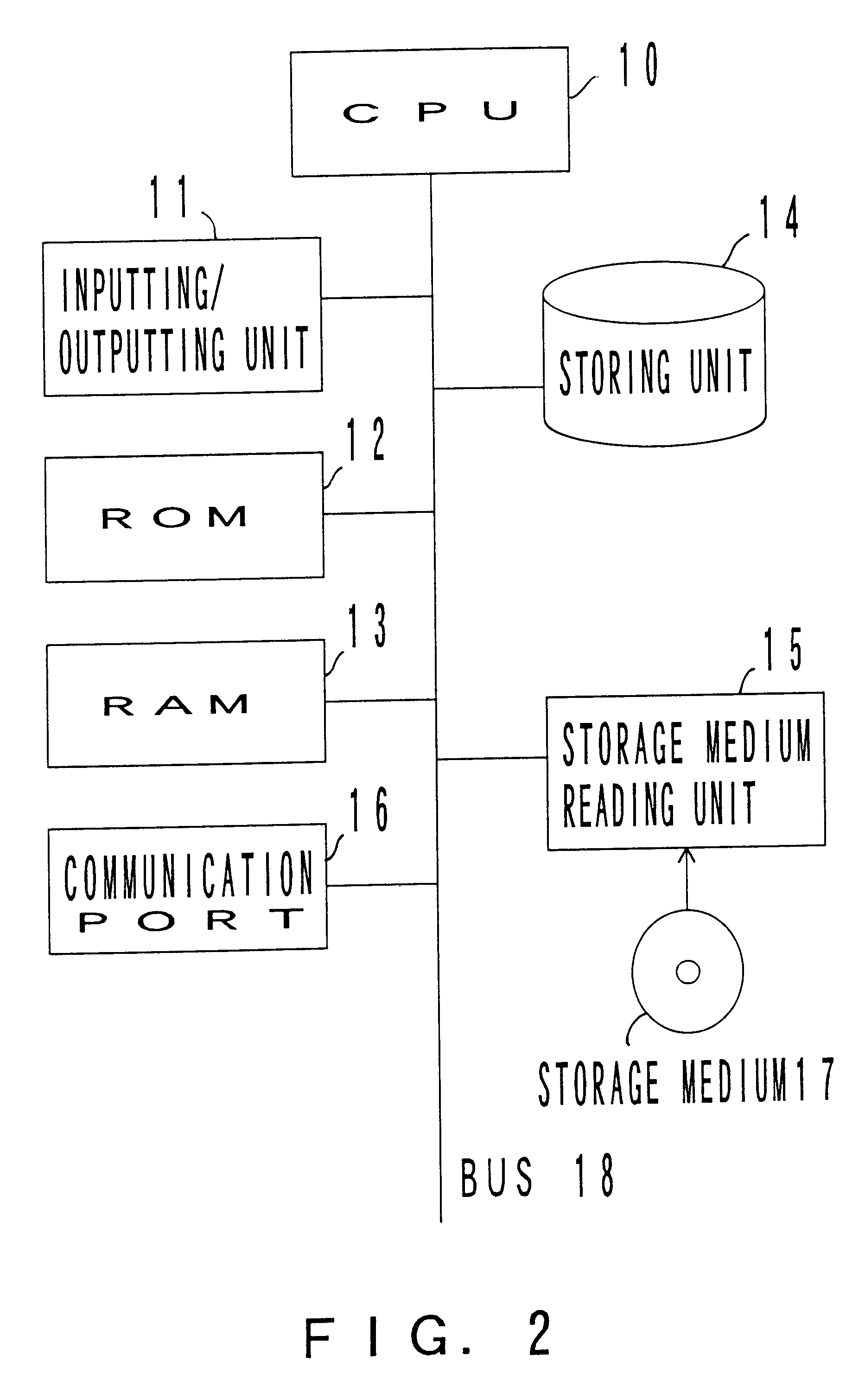
FIG. 2 is a schematic diagram showing the structure of hardware of a system according to the present invention. It should be noted that as long as the system is an information terminal unit (for example, a personal computer) that has hardware to which a window system can be installed, the system according to the present invention is not limited to the structure shown in FIG. 2.

As the structure of the hardware, the system has a CPU 10 that performs various calculations. A bus 18 is connected to the CPU 10. In addition, an inputting / outputting unit 11, a ROM 12, a RAM 13, a storing unit 14, a communication port 16, and a storage medium reading unit 15 are connected to the bus 18.

The inputting / outputting unit 11 is composed of, for example, a keyboard and a display unit. In particular, to use the window system, the inputting / outputting unit 11 normally includes a mouse.

The ROM 12 stores a basic input / output system such as BIOS. When operation of the system shown in FIG. 2 is started, t...


PUM


Abstract

In the window system, patterns of windows, icons, buttons, and so forth are defined in a body coordinate system. The window system has definition data for a process corresponding to a button and so forth. The definition data has a displaying portion including a display command for displaying a window and so forth. The displaying portion causes a window and so forth to be displayed on a display unit corresponding to designated coordinate values. The displaying portion has a three-dimensional displaying portion that rearranges each object from the body coordinate system to the world coordinate system corresponding to designated coordinate values and projects the resultant object on a screen at a designated view point. The three-dimensional displaying portion supplies coordinate values for three-dimensionally displaying the object to the displaying portion.

Description

1. Field of the InventionThe present invention relates to a system for three-dimensionally displaying windows of a window system.2. Description of the Related ArtAs process performance of information processing units has been improved, various window systems have been used. In particular, as the process performance of personal computers has been improved, graphics-based operating environments have been provided as window systems for personal computers used by end users. Thus, a user-friendly interface is provided for novice users who are not familiar with operating systems.FIGS. 1A and 1B are schematic diagrams showing examples of windows displayed on screens. In a conventional window system, windows are two-dimensionally displayed on a screen 110 of a display unit. In FIG. 1A, windows 111, 112, and 113 are opened on the screen 110. However, the windows 111, 112, and 113 overlap with each other. The window 111 that the user is currently using is displayed as the top window on the sc...

Claims


Application Information

Patent Timeline
Patent Type & Authority Patents(United States)
IPC IPC(8): G06F3/033G06F3/14G06F3/048G06F3/0481G09G5/14G09G5/36
CPCG06F3/04815
Inventor NEGISHI, HISASHITSUCHI, YASUHIKONAKAGAKI, YOSHIHIRO
Owner FUJITSU LTD
Why Eureka
Try Eureka