Screw-tightening spindle fitted with a removable chuck

a technology of screw-tightening spindles and chucks, which is applied in the direction of turning apparatuses, fastening means, ropes and cables for vehicles/pulleys, etc. it can solve the problems of reducing productivity, achieve the effect of reducing the risk of sleeve and cylindrical support member being accidentally separated, and performing much more quickly

Inactive Publication Date: 2003-04-08
SERAC GROUP
View PDF15 Cites 18 Cited by
  • Summary
  • Abstract
  • Description
  • Claims
  • Application Information

AI Technical Summary

Benefits of technology

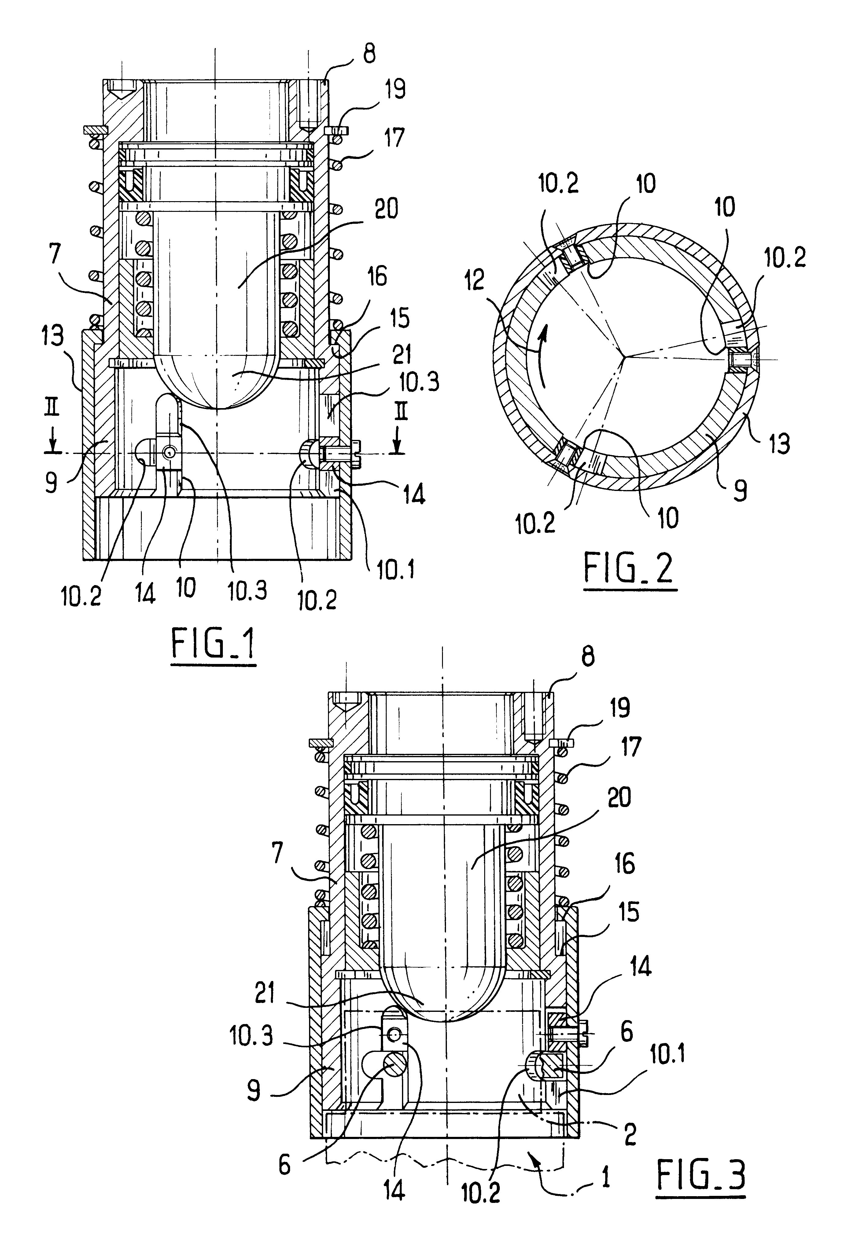
Thus, coupling is performed merely by axially displacing the cylindrical support member relative to the sleeve, followed by turning to bring the stud into the end portion of the slot. These two displacements can be performed in a single movement such that mounting the cylindrical support member on the sleeve and removing it therefrom can be performed much more quickly than with a nut while nevertheless ensuring positive locking of the jaw-support member relative to the sleeve.
Advantageously, the second segment of the slot extends from one side of the first segment of the slot such that when the sleeve is rotated, the stud of the cylindrical support member tends to be urged towards the end portion of the second segment of the slot. Thus, the risk of the sleeve and the cylindrical support member being accidentally separated is further reduced.
In a particular embodiment, the first slot segment extends substantially along an axial direction of the sleeve, and the second slot segment extends along a substantially circumferential direction of the sleeve and preferably, the third segment extends in line with the first segment. This makes the slot particularly simple to make.

Problems solved by technology

Such stoppage reduces productivity.

Method used


Image

  • Screw-tightening spindle fitted with a removable chuck
  • Screw-tightening spindle fitted with a removable chuck
  • Screw-tightening spindle fitted with a removable chuck

Examples


Embodiment Construction

The screw-tightening chuck of the invention is for coupling in conventional manner to a rotary drive shaft, e.g. installed in a carousel for closing receptacles that are provided with caps.

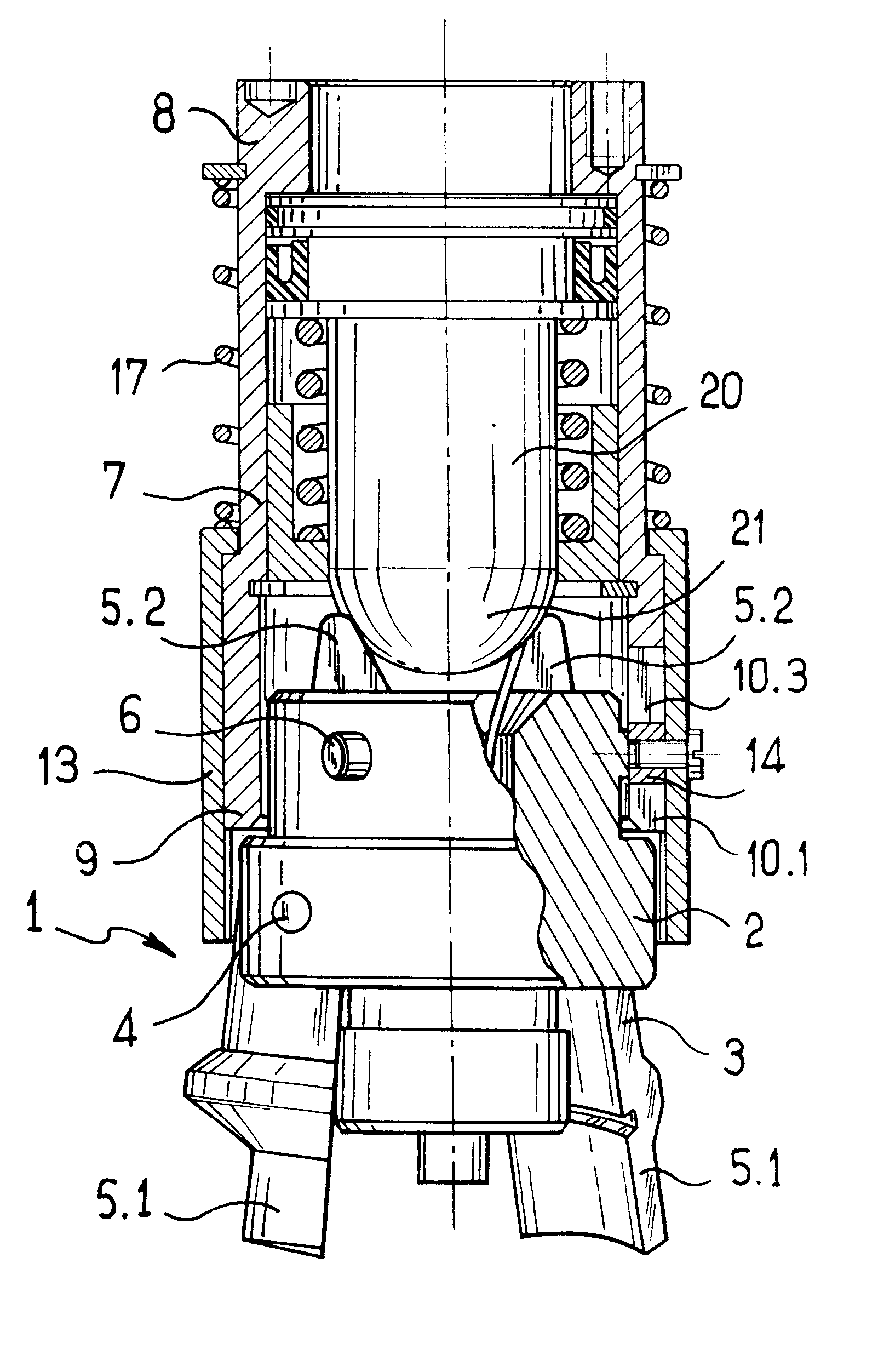
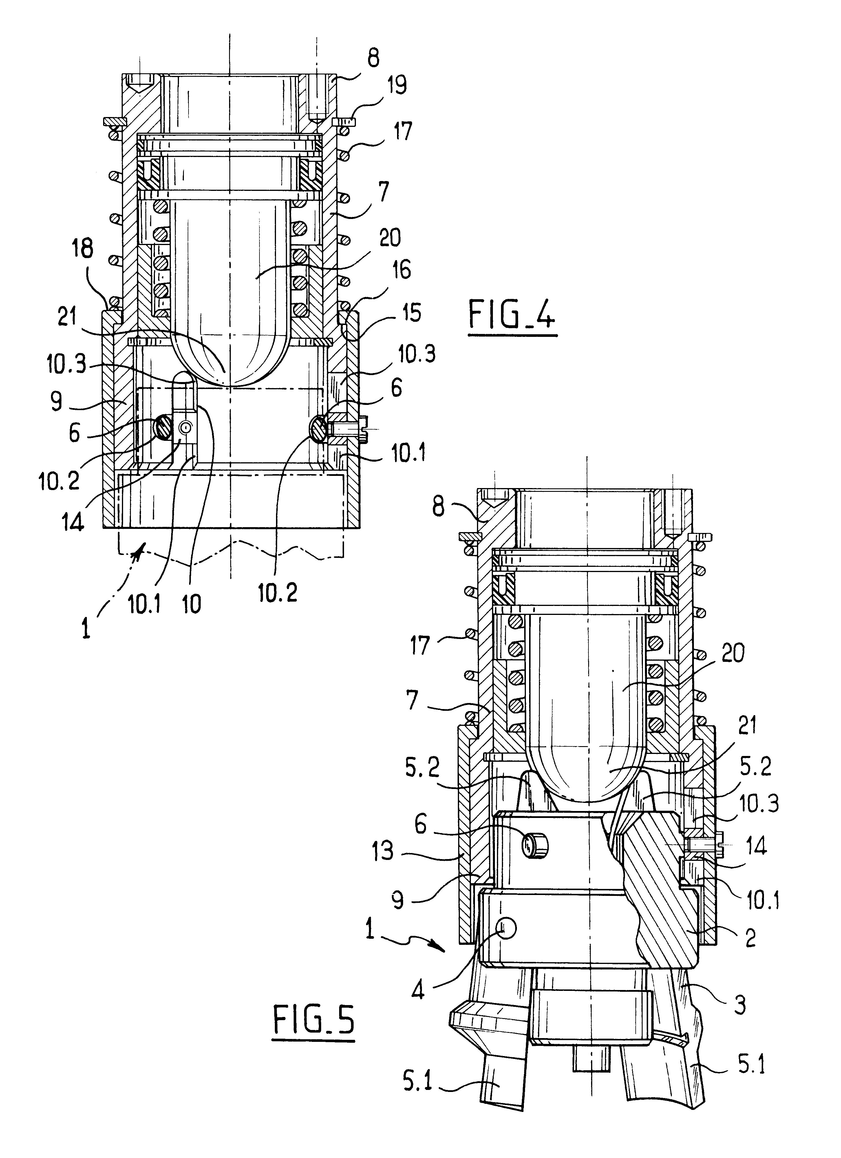
With reference to FIGS. 3 to 5, the screw-tightening spindle comprises a cap-holding chuck 1 which itself comprises a cylindrical support member 2 having jaws 3 mounted thereon to pivot about axes 4. Each jaw has a cap-holding end 5.1 and an opposite, lever-forming end 5.2 for actuating the jaw 3. Studs 6 project radially from the outer surface of the cylindrical support member 2. In this case, there are three such studs disposed at 120.degree. intervals from one another. In order to ensure that FIGS. 3 and 4 are easy to read, the chuck 1 is shown for the most part in chain-doted lines with only its studs 6 being shown in section in these figures.

With reference also to FIGS. 1 and 3, the screw-tightening spindle also comprises a sleeve 7 having an end portion 8 for fixing to the rotary drive shaft...


PUM


Abstract

A screw-tightening spindle comprising a drive sleeve associated with a chuck comprising a cylindrical support member fitted with moving jaws, the cylindrical support member being provided externally with at least one stud extending radially outwards, the sleeve including at least one slot having a first segment opening out in a free edge of the sleeve and a second segment having an end portion forming an angle relative to the sleeve suitable for retaining the stud in the end portion of the slot when the stud is engaged therein, the sleeve being fitted with a ring having at least one stop extending radially inwards and received in the slot, the ring being mounted on the sleeve to slide between a locking position in which the stop extends in the first segment of the slot in register with the second segment, and an unlocking position in which the stop is retracted into a third segment of the slot.

Description

The present invention relates to a screw-tightening spindle suitable for use in particular in a bottling plant for tightening caps onto the necks of receptacles.Screw-tightening spindles are known that comprise a drive socket having an end provided with a threaded collar onto which there is screwed a nut which is secured to a cap-holding chuck which comprises a cylindrical support member fitted with moving jaws. The combination of the threaded collar and the nut provides a removable coupling, thereby enabling the chuck to be replaced for maintenance purposes and more generally making it possible to have a set of interchangeable chucks that match different types of cap. In order to ensure that the jaw-support member is not removed accidentally, the screw pitch of the nut must be irreversible, i.e. the pitch must be short, requiring the nut to perform a plurality of tightening or loosening turns during installation or removal of the chuck. In addition, a plurality of screw-tightening ...

Claims


Application Information

Patent Timeline
Patent Type & Authority Patents(United States)
IPC IPC(8): B67B3/20B67B3/00B23B5/22
CPCB67B3/2066B67B2201/10Y10T403/581Y10T403/58Y10T403/7007Y10T279/17051Y10T279/17888F16B2200/69
Inventor GRUSON, BERTRAND
Owner SERAC GROUP
Why Eureka
Try Eureka