Shunt of squib

a squib and shunt technology, applied in the direction of pedestrian/occupant safety arrangement, coupling device connection, vehicular safety arrangement, etc., can solve the problem of higher cos

Inactive Publication Date: 2003-04-08
TOYOTA JIDOSHA KK +1
View PDF6 Cites 32 Cited by
  • Summary
  • Abstract
  • Description
  • Claims
  • Application Information

AI Technical Summary

Benefits of technology

In this case, if the female connector is inserted obliquely, the female connector will strike on the annular wall and halt. As the depth of insertion of the female connector into the fitting hole in the axial direction of the pins is not more than the length from the top end of the pins to the top of the annular wall, the female connector will not press on the pins. Hence the female connector will not force the pins. Accordingly, the pins will not be deformed, and when the female connector is reinserted properly this time, the female connector will be connected to the pins reliably In this way, the problem can be eliminated and the cost can be lowered.
Similar actions may be obtained by making the housing of the inflator thicker or reducing the height of the pins from the bottom of the socket. However, as the configurations of the inflators and squibs tend to be unified to recommended configurations, the above-mentioned changes will merely invite confusion by increasing the kinds of inflators and squibs. In contrast to them, if the shunt of the present invention is used, the female connector can be prevented from forcing the pins without altering the configurations of the inflator and the squib. Thus the shunt of the present invention is useful.

Problems solved by technology

In either case, it will result in a higher cost.
However, as the configurations of the inflators and squibs tend to be unified to recommended configurations, the above-mentioned changes will merely invite confusion by increasing the kinds of inflators and squibs.

Method used


Image

  • Shunt of squib
  • Shunt of squib
  • Shunt of squib

Examples


first embodiment

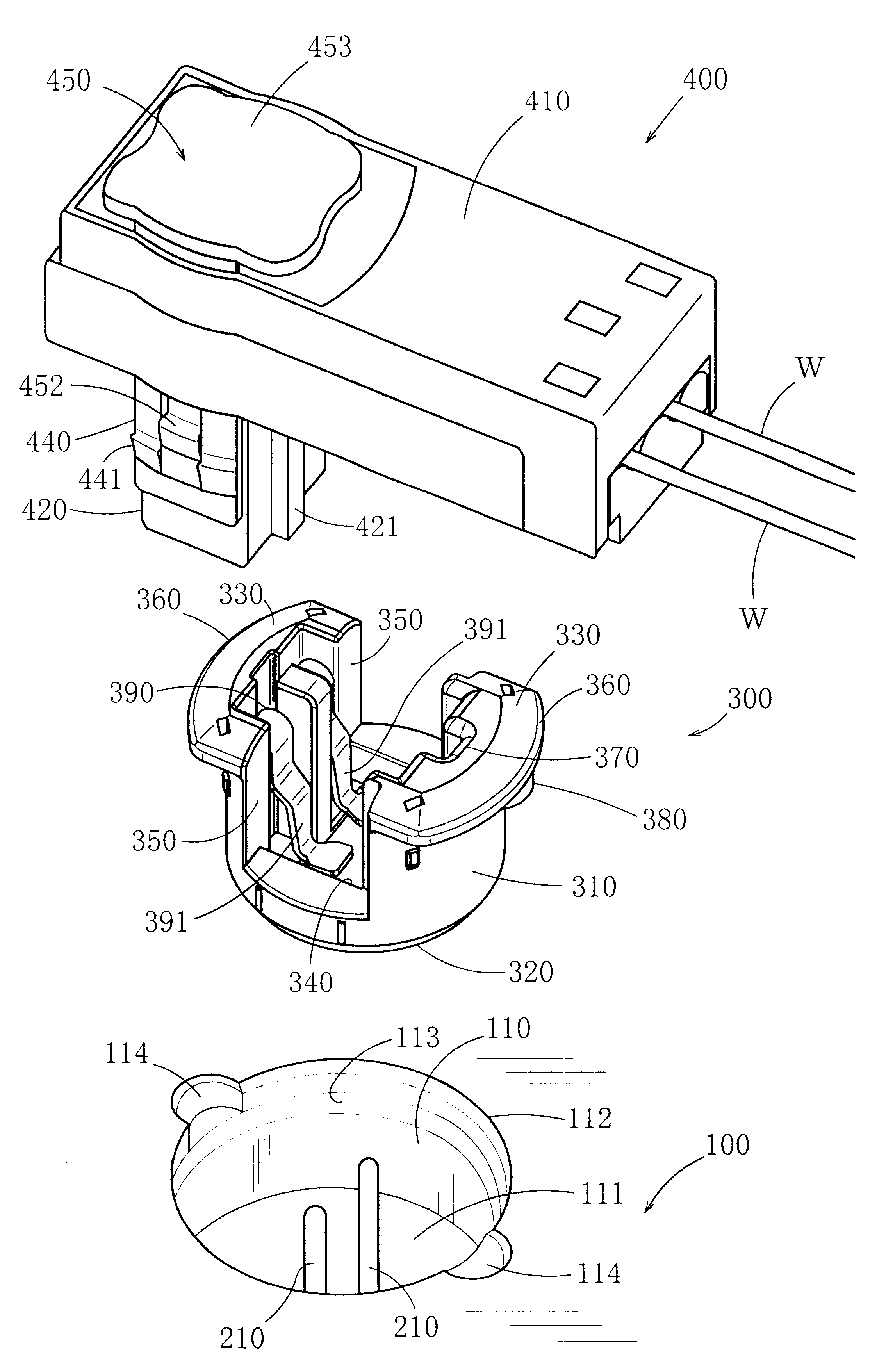
In the following, embodiments of the shunt of the squib according to the present invention will be described. FIG. 1 shows the shunt of the first embodiment and members around the shunt. 100 denotes a housing of an inflator. Inside the housing 100 of the inflator, is fixed a squib 200 that receives electric energy to generate heat, and an initiator and a gas generator are arranged around the squib 200. On the back side of the inflator, a folded airbag is stored. When the squib 200 receives electric energy to generate heat, the initiator will be ignited, and, this in turn will make the gas generator generate gas, and this gas will inflate the airbag.

A cylindrical socket 110 is concavely formed in the external face of the housing 100 of the inflator. The squib 200 is fixed on the back side of this socket 110. A pair of pins 210, which are connected to a stored heater, protrude from the squib 200, said pair of pins 210 rising at the center of the socket 110 from the bottom 111 to a poi...

second embodiment

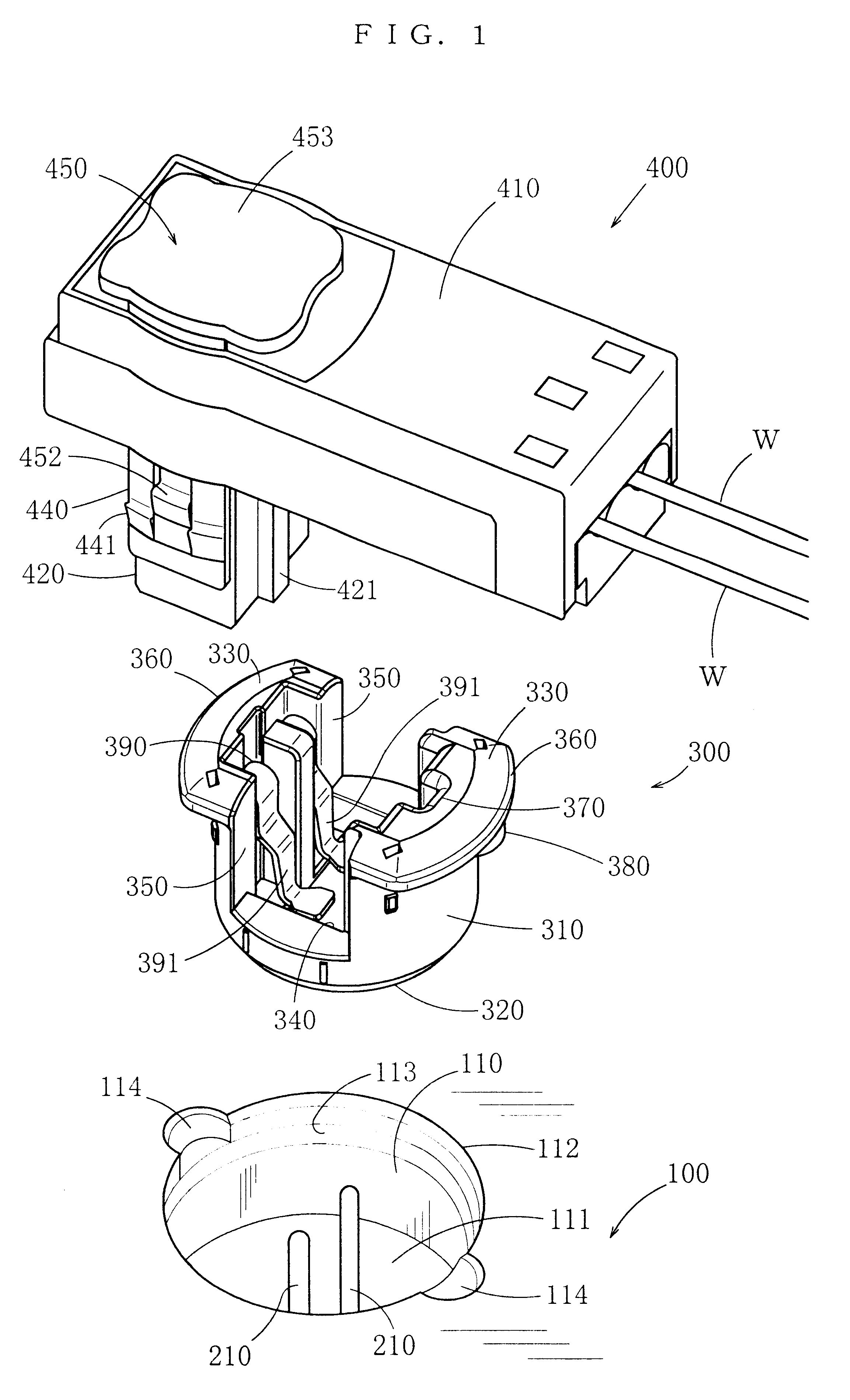
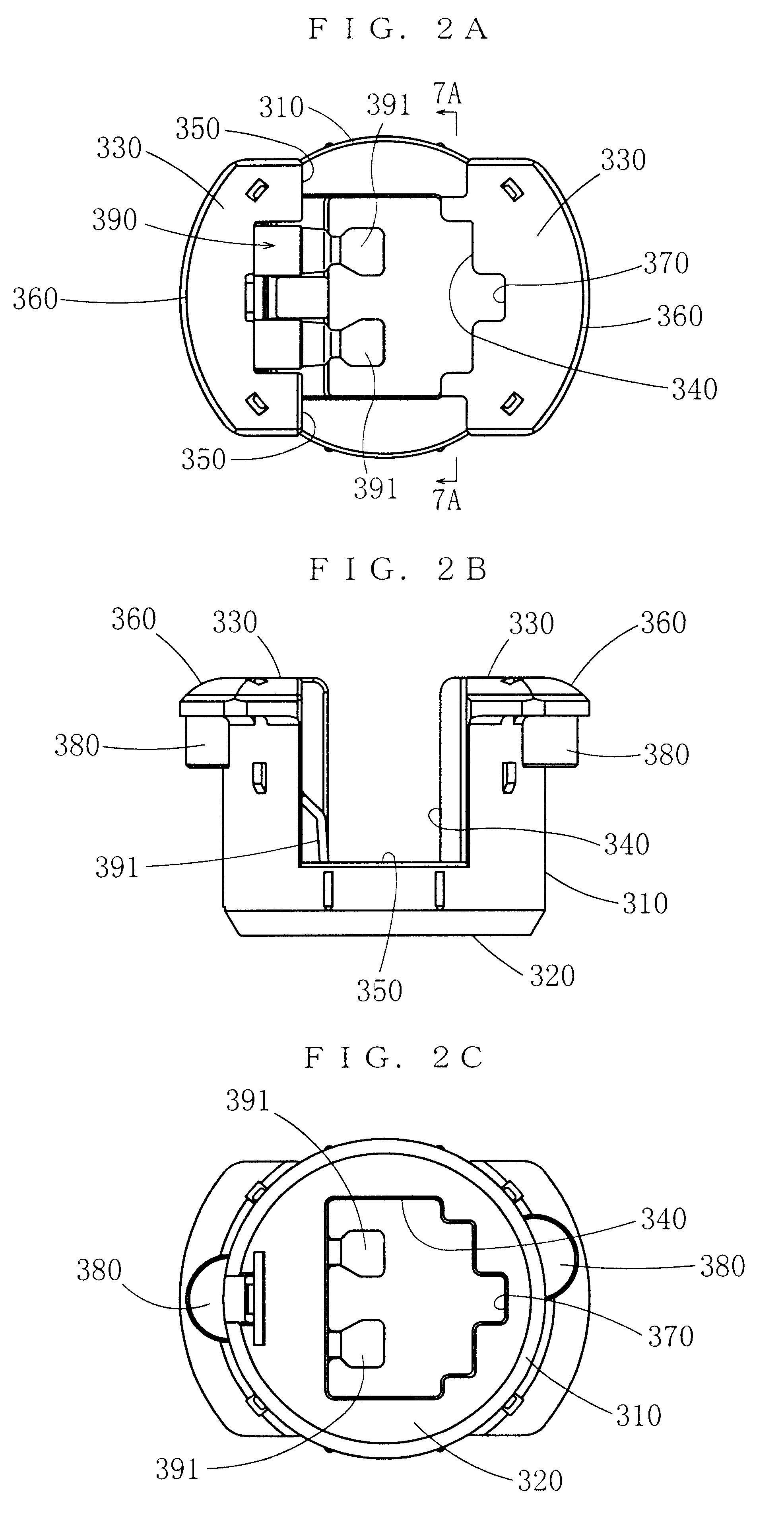
The second embodiment exhibits actions and effects similar to those of the first embodiment. In the second embodiment, as the gap between the annular wall 310 and the internal wall of the socket 110 is covered by the brim all over the circumference, the female connector will not be caught on the gap and it will be smoothly fitted into the shunt 300. Thus the efficiency of fitting the female connector 400 into the shunt 300 is improved further. Moreover, as the external circumferential edge of the top 330 is annular and continuous, the strength of the annular wall 310 is improved. Furthermore, the annular continuous external circumferential edge of the top 330 prevents any objects from coming into the fitting hole 340, and the function of protecting the short-circuit piece 390 is improved more. This is particularly effective when the shunt 300 is kept in an isolated state such as during transportation of the shunt 300.

The constructions of the female connectors 400 of the above-mentio...


PUM


Abstract

The present invention aims to prevent forcing of pins when a female connector is obliquely inserted into a shunt.A shunt fits into a cylindrical socket concavely formed in an external face of a housing of an airbag inflator and short-circuits of a pair of contact pins of a squib of the inflator. These pins rise at the center of the socket from the bottom to a point near to the opening. The shunt includes an annular wall having a fitting hole into which the pins enter from the bottom side of the center thereof and into which a female connector fits from the top side, and a short-circuit piece provided on the annular wall, which will contact both of the pins when the shunt is fitted into the socket, and will be pushed to move away from the pins when the female connector is fitted into the fitting hole. To prevent forcing or bending of the pins if the female connector is improperly obliquely inserted into the fitting hole of the shunt, the height of the annular wall is not less than the sum of the depth of insertion of the female connector into the fitting hole in the axial direction of the pins when the female connector is inserted obliquely plus the height of the pins from the bottom of the socket.

Description

1. Field of the InventionAn inflator, which feeds gas into an airbag to inflate it, has a squib. To supply electric energy to this squib, a female connector is connected to a pair of pins of the squib. The present invention relates to a shunt, which short-circuits the pair of pins of the squib until the female connector is connected to the pair of pins.2. Related ArtA shunt is known, which is fitted into a cylindrical socket being concavely formed in an external face of a housing of an inflator and short-circuits a pair of pins of a squib, said pair of pins rising at the center of the socket from the bottom up to the opening. For example, Japanese Patent unexamined publication gazette Heisei 6-208867 discloses a shunt that is called a short-circuit insert. This shunt has a short-circuit clip and uses this short-circuit clip to short-circuit a pair of pins of a squib so as to prevent the squib from false actuation. After an inflator is fitted into a vehicle, when a female connector i...

Claims


Application Information

Patent Timeline
Patent Type & Authority Patents(United States)
IPC IPC(8): B60R21/01H01R13/703H01R13/70H01R13/639B60R21/26B60R21/264H01R11/01H01R13/46H01R31/08
CPCB60R21/017H01R13/7032H01R13/639B60R2021/01006B60R21/01
Inventor WAKUI, MASANORINISHIDA, ATSUSHINAGAMINE, AKIRAIIDA, TAKASHI
Owner TOYOTA JIDOSHA KK
Why Eureka
Try Eureka