Conveyor roller with telescoping axle having tapered ends

a conveyor roller and telescopic technology, which is applied in the direction of conveyor parts, conveyor-ways, packaging, etc., can solve the problems of generating even more noise, loosing the fit between the shaft and the frame, and causing noise and wear on both the shaft and the apertur

Inactive Publication Date: 2003-04-15
INTELLIGRATED HEADQUATERS LLC
View PDF49 Cites 24 Cited by
  • Summary
  • Abstract
  • Description
  • Claims
  • Application Information

AI Technical Summary

Benefits of technology

According to this invention, the mounting of a conveyor roller to the conveyor frame members is improved by the use of a roller shaft which is telescoping and has tapered ends. The roller shaft preferably is of two-piece telescoping tubular construction with a spring positioned inside the telescoping tubular members urging the members away from each other. The tubular construction of the shaft or axle provides added strength in the middle of the span compared to a solid hex axle and keeps the axle aligned with the bearings without being distorted out of alignment when subjected to a load.
The ends of the shaft are tapered outwardly and engage the mounting holes in the conveyor frame to eliminate play between the shaft and the mounting holes. The tapered ends allow replacement rollers to be placed into mounting holes that have been enlarged by wear and still seat firmly.

Problems solved by technology

The shaft is generally loosely positioned in the mounting aperture and vibration and loading conditions of the roller causes the shaft to bounce, causing noise and wear on both the shaft and the aperture.
Over time, the wear from shaft vibration results in enlargement of the mounting aperture, creating an even looser fit between the shaft and the frame and generating even more noise.
Eventually, the shaft vibration causes the frame to cut through the roller shaft, resulting in the roller dropping out of the frame.

Method used


Image

  • Conveyor roller with telescoping axle having tapered ends
  • Conveyor roller with telescoping axle having tapered ends

Examples


Embodiment Construction

The following detailed description illustrates the invention by way of example and not by way of limitation. This description will clearly enable one skilled in the art to make and use the invention, and describes several embodiments, adaptations, variations, alternatives and uses of the invention, including what I presently believe is the best mode of carrying out the invention. As various changes could be made in the constructions without departing from the scope of the invention, it is intended that all matter contained in the description or shown in the accompanying drawings shall be interpreted as illustrative and not in a limiting sense.

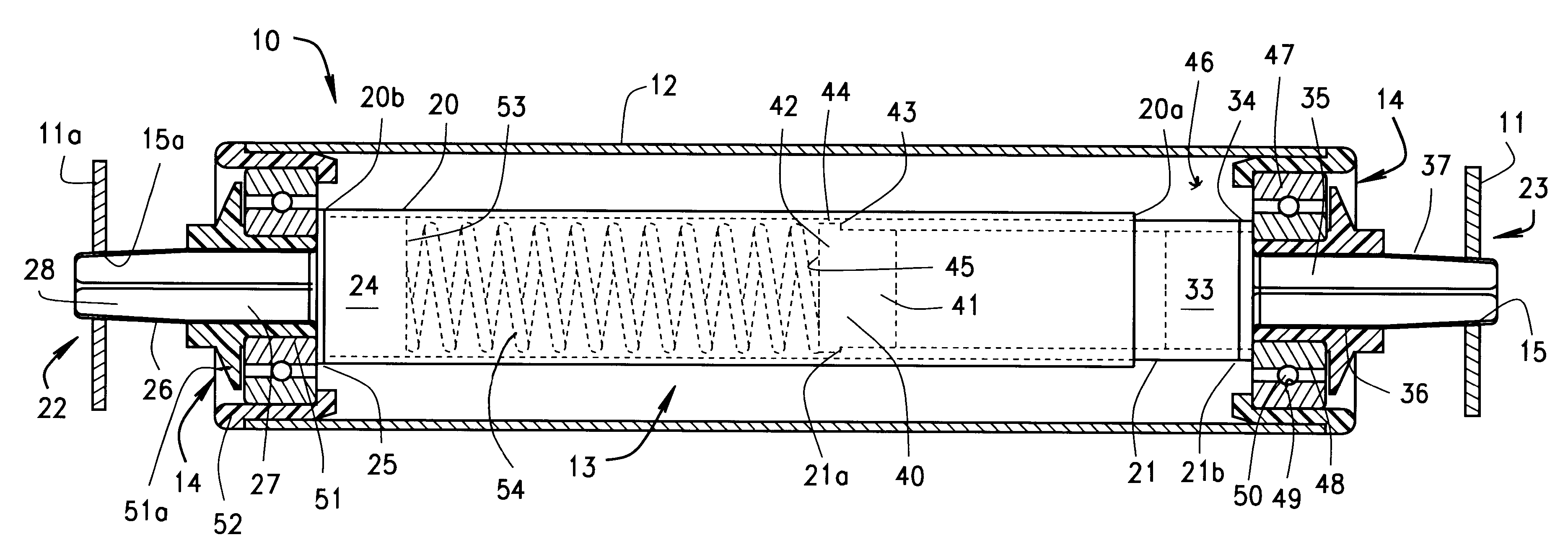
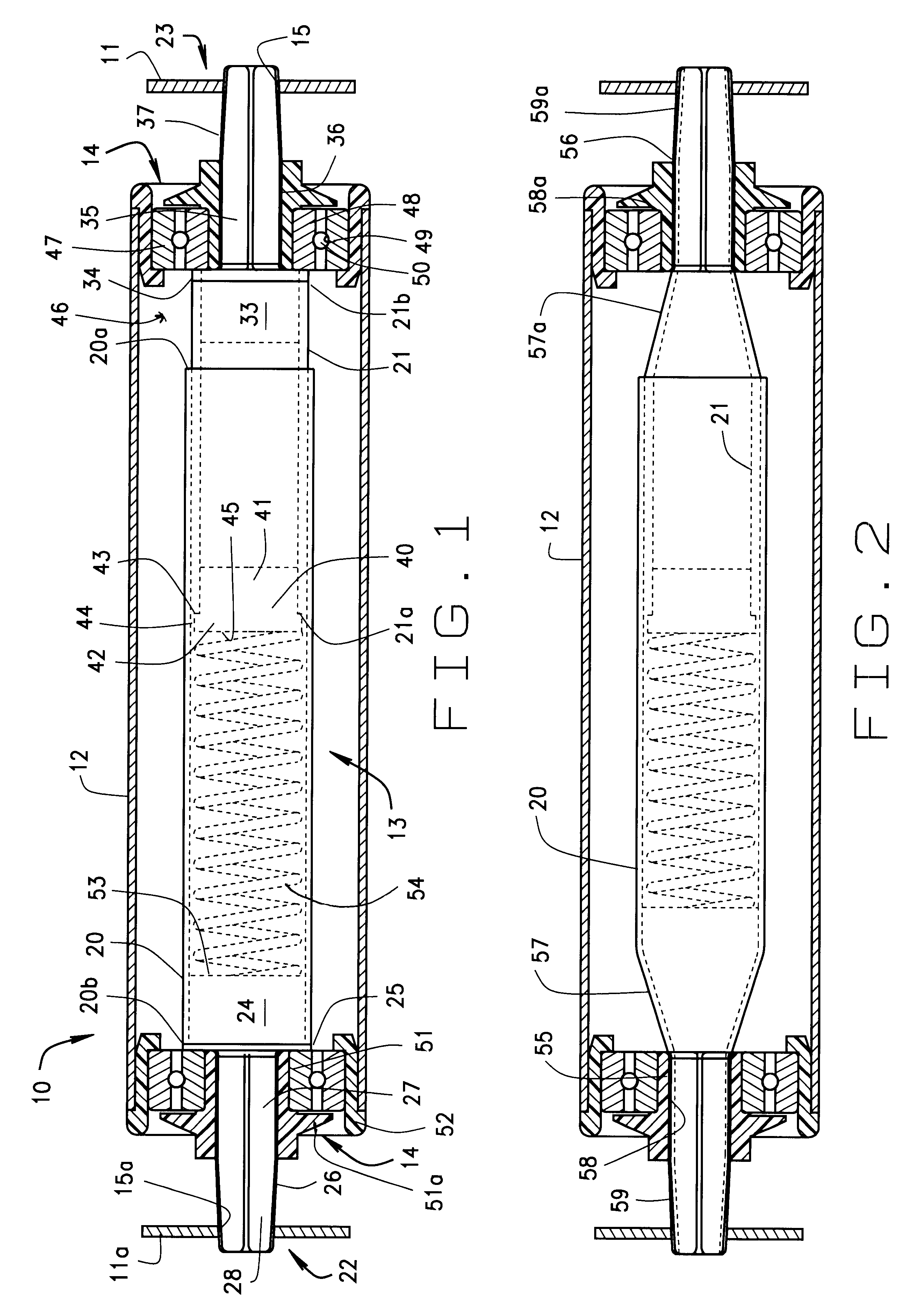
FIG. 1 shows a conveyor roller assembly 10 mounted between conveyor frame members 11,11a. The roller assembly 10 comprises a cylindrical roller tube 12 rotatably mounted on a shaft or axle assembly 13 by bearing assemblies 14. The frame members have openings 15,15a therein to mount the roller assemblies 10.

The shaft assembly 13 is the essential...


PUM


Abstract

A conveyor roller having a spring loaded telescoping tubular axle with tapered hexagonal shaped ends allowing quick replacement in the side frame openings of a conveyor when the openings are worn to an oversize. The tapered hex ends also provide for a tight fit between hex ends and hex holes in the frame to lessen relative motion (rattling) between the two surfaces that causes wear and noise. The roller can be installed from either side of the conveyor because the axle is collapsible from either end.

Description

CROSS-REFERENCE TO RELATED APPLICATIONS STATEMENTREGARDING FEDERALLY SPONSORED RESEARCH OR DEVELOPMENTNot Applicable1. Field of the InventionThe present invention relates generally to rollers for roller conveyors and more specifically to a conveyor roller with a telescoping shaft having tapered ends.2. Description of Related ArtA conveyor roller generally is rotatably mounted on a shaft, which, in turn, is mounted in openings located in laterally spaced side frame members of the conveyor.The shaft is generally loosely positioned in the mounting aperture and vibration and loading conditions of the roller causes the shaft to bounce, causing noise and wear on both the shaft and the aperture. Over time, the wear from shaft vibration results in enlargement of the mounting aperture, creating an even looser fit between the shaft and the frame and generating even more noise. Eventually, the shaft vibration causes the frame to cut through the roller shaft, resulting in the roller dropping ou...

Claims


Application Information

Patent Timeline
Patent Type & Authority Patents(United States)
IPC IPC(8): B65G39/10B65G39/12
CPCB65G39/12B65G2207/32
Inventor GAMACHE, BRIAN L.
Owner INTELLIGRATED HEADQUATERS LLC
Why Eureka
Try Eureka