Mass flow rate measuring device

Inactive Publication Date: 2003-05-06
KRONE GMBH
View PDF11 Cites 77 Cited by
  • Summary
  • Abstract
  • Description
  • Claims
  • Application Information

AI Technical Summary

Problems solved by technology

That, however, does not completely compensate for the above-mentioned varying environmental operating parameters.
However, the parameters of the mass flowmeter such as its zero point and its sensitivity cannot be determined that way.
Other problems of mass flowmeters with only one straight Coriolis conduit derive from the fact that the oscillating components, which essentially means the Coriolis conduit proper, transfer oscillating forces or torque to the points at which the Coriolis conduit is clamped, forces which especially in the case of mass flowmeters with only one straight Coriolis conduit cannot be absorbed without a reactive effect.
This can cause oscillatory energy to be asymmetrically drained from the Coriolis co

Method used


Image

  • Mass flow rate measuring device
  • Mass flow rate measuring device
  • Mass flow rate measuring device

Examples


Example

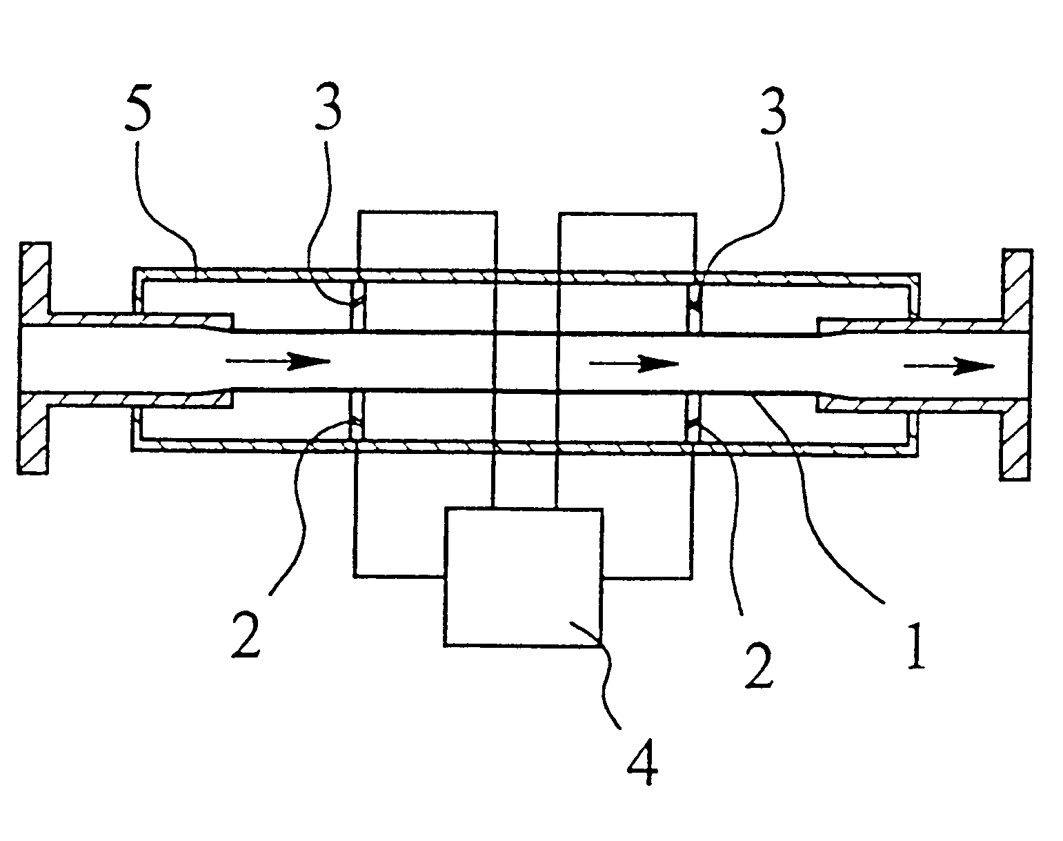
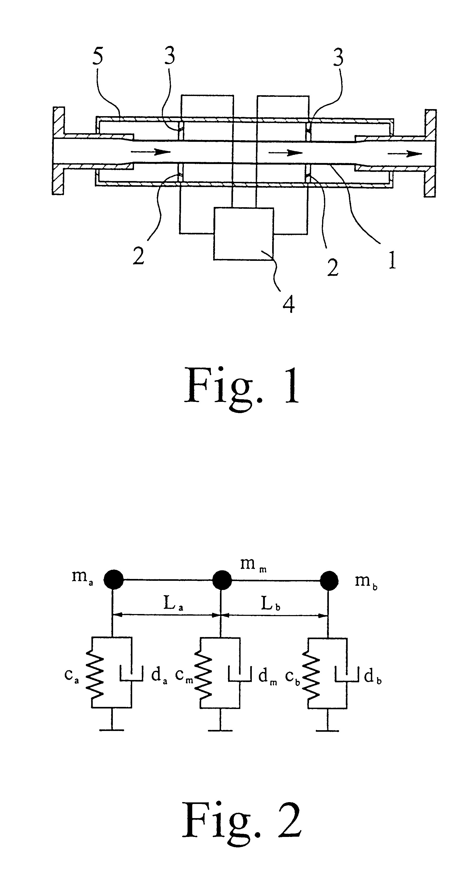
FIG. 1 is a simplified block diagram of the mass flowmeter according to the preferred embodiment of this invention. The mass flowmeter consists essentially of a Coriolis conduit 1, two oscillators 2 serving to excite the Coriolis conduit 1, two detectors 3, a digital signal processor 4 and a carrier tube 5. Each of the two oscillators 2 is located in the same axial region as one of the detectors 3 and is in each case positioned at the same distance from the center of the Coriolis conduit 1. A fluid whose mass flow rate is to be measured flows through the Coriolis conduit 1 in the direction of the arrow. As in the case of many conventional Coriolis mass flowmeters, the Coriolis conduit 1 is surrounded by a carrier tube 5 which is attached at both the input and the output ends of the Coriolis conduit 1. In the case of the mass flowmeter according to the preferred embodiment of this invention, all of the signal processing, regulating and control functions are fully digital and are hand...


PUM


Abstract

A method for online-determination of at least one characteristic value of a mass flowmeter operating by the Coriolis principal and incorporating a fluid-conducting Coriolis conduit. The method includes the following steps of exciting the Coriolis conduit in a first oscillation pattern, exciting the Coriolis conduit in a second oscillation pattern, the second oscillation pattern being different from the first oscillation pattern, capturing the response of the Coriolis conduit to the excitation in the first oscillation pattern and in the second oscillation pattern and determining at least one characteristic value of the mass flowmeter by evaluating the response of the Coriolis conduit with the aid of a model in real time during operation of the mass flowmeter.

Description

Not Applicable1. Field of the InventionThis invention relates to a mass flowmeter operating by the Coriolis principle, incorporating a fluid-conducting Coriolis conduit, at least two oscillators associated with and exciting the Coriolis conduit, as well as at least two detectors associated with the Coriolis conduit for capturing Coriolis forces and / or Coriolis-force-derived Coriolis oscillations, said Coriolis conduit permitting excitation in a first oscillation pattern and in an oscillation pattern independent of the first oscillation pattern. The invention further relates to a method for determining the mass flow employing a mass flowmeter operating by the Coriolis principle and incorporating a fluid-conducting Coriolis conduit, at least two oscillators associated with and exciting the Coriolis conduit, as well as at least two detectors associated with the Coriolis conduit for capturing Coriolis forces and / or Coriolis-force-derived Coriolis oscillations, said Coriolis conduit perm...

Claims


Application Information

Patent Timeline
IPC IPC(8): G01F1/84G01F1/76
CPCG01F1/849G01F1/8436
Inventor KOLAHI, KOURUSH
Owner KRONE GMBH
Why Eureka
Try Eureka