Baitfish chunking apparatus

a technology for chunking apparatus and fish, which is applied in the direction of metal working apparatus, fish processing, meat processing plants, etc., can solve the problems of increasing the effort required to operate the '533 device, the body of fish, and revealing certain deficiencies

Inactive Publication Date: 2003-05-06
NEDELKA JOHN
View PDF23 Cites 52 Cited by
  • Summary
  • Abstract
  • Description
  • Claims
  • Application Information

AI Technical Summary

Problems solved by technology

Although the device described in U.S. Pat. No. 5,562,533 is useful, certain deficiencies become apparent when the chunking device is employed in various typical chunking applications.
For example, baitfish are often purchased frozen and increased effort is therefore required to operate the '533 device when chunking such frozen fish.
Conversely, once bait fish have thawed, another problem arises due to the unique co...

Method used


Image

  • Baitfish chunking apparatus
  • Baitfish chunking apparatus
  • Baitfish chunking apparatus

Examples


Embodiment Construction

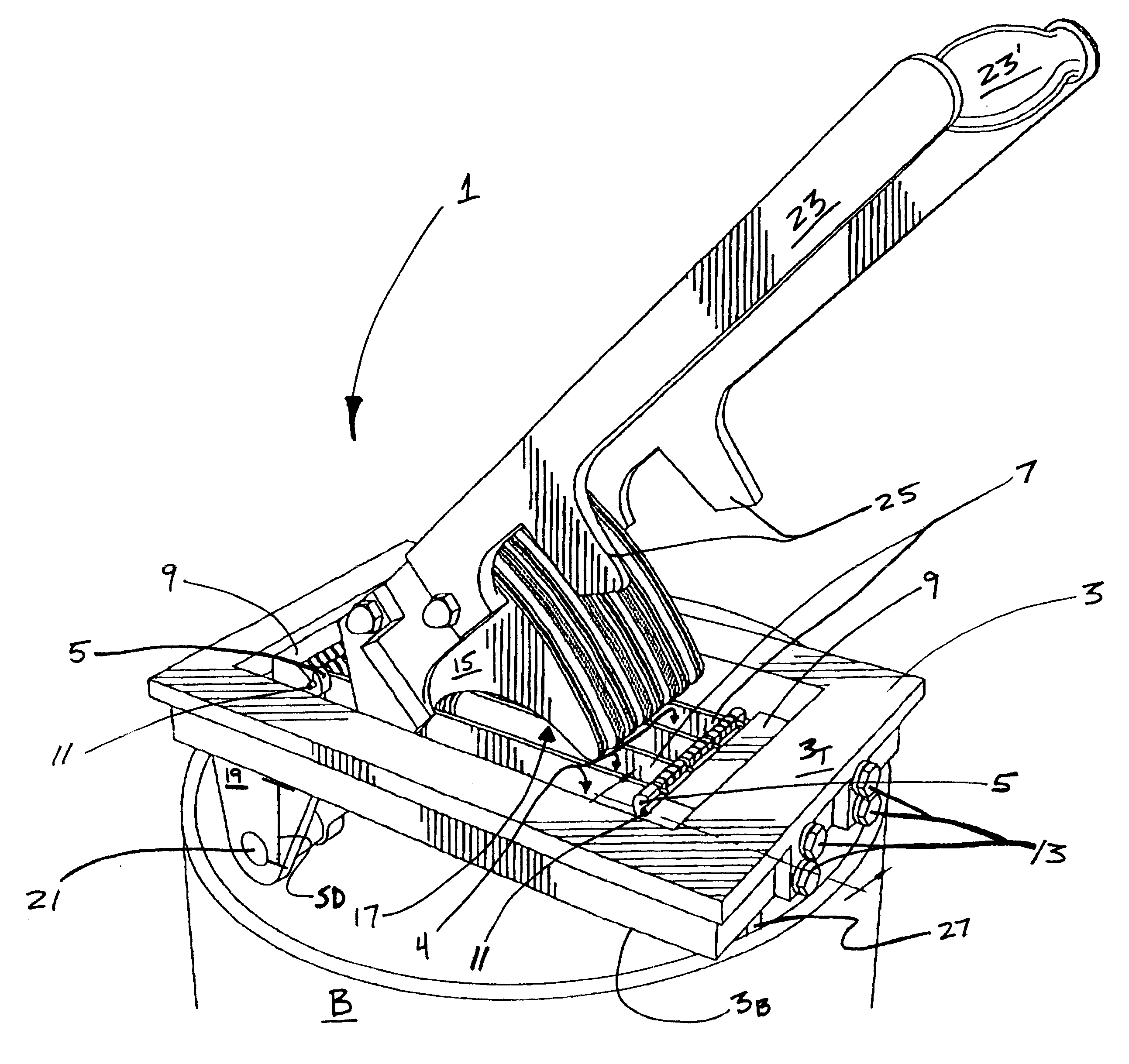
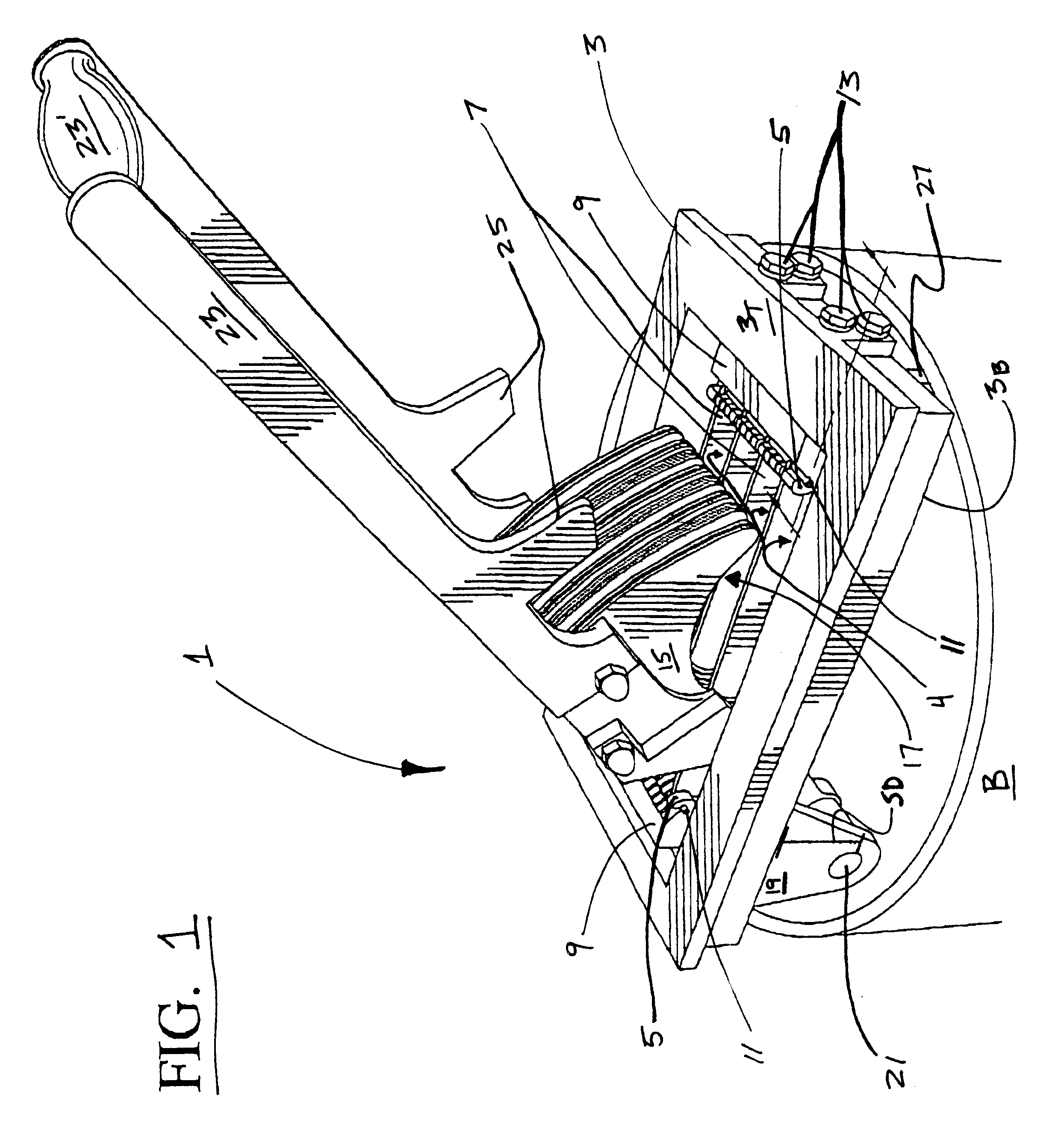
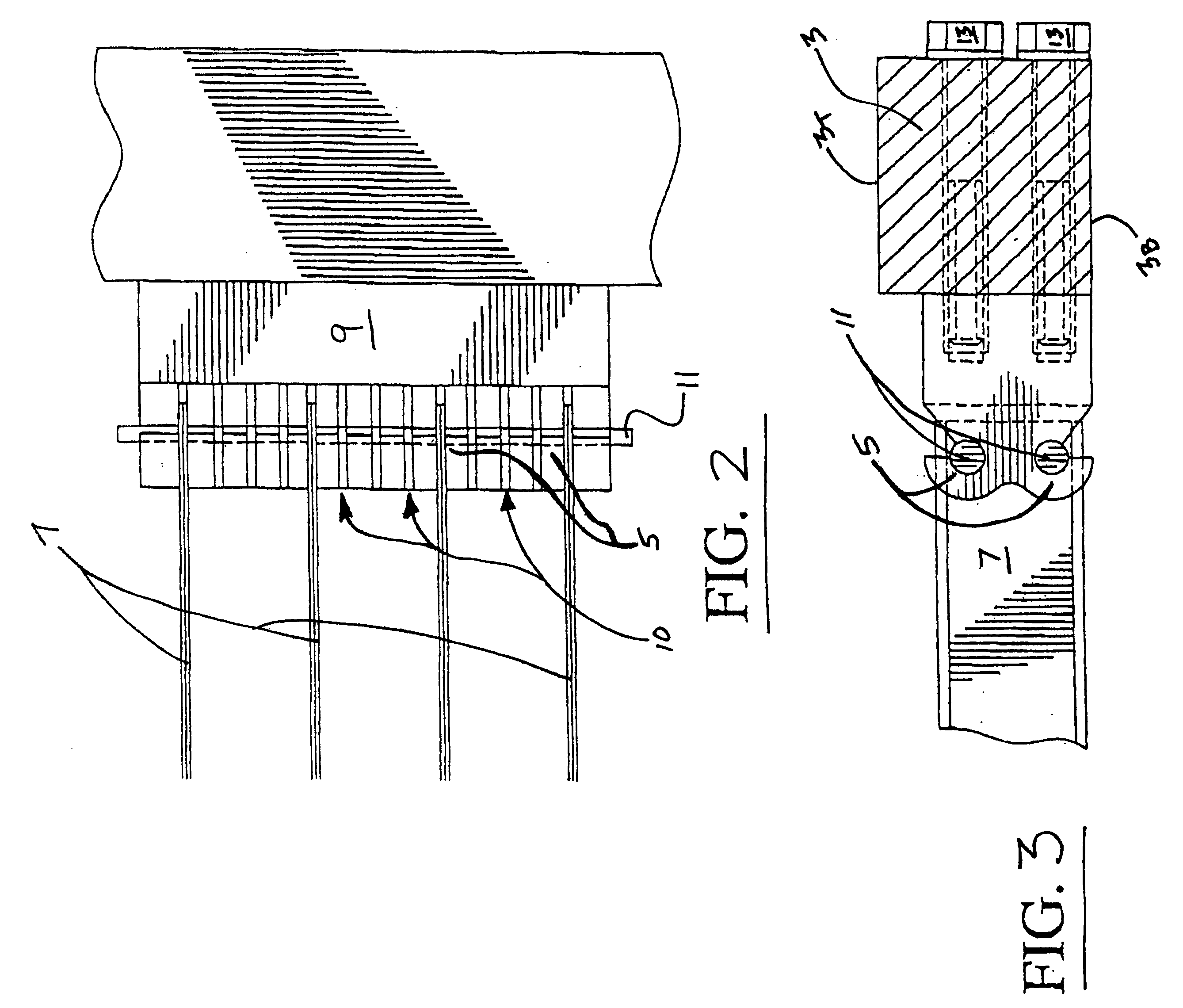
Referring initially to FIG. 1, therein is illustrated one exemplary embodiment of the chunking apparatus according to the subject invention. As illustrated, chunking apparatus 1 comprises a base member 3 which frames a cavity 4. Within cavity 4, a plurality of blades 7 are spaced therein, mounted at each of their ends between two mount blocks 9. As may be seen more clearly in FIGS. 2-3, each mount block 9 includes a pair of pins seats 5 in which locking pins 11 are seated to secure blades 7 at their ends to the respective mount blocks (through pin apertures in the blades not shown). Mount blocks 9, in turn, are secured to base member 3 in conventional fashion employing bolts 13 on either side of the base member.

In certain embodiments, and as illustrated in FIG. 2, the distance between blades 7 may be varied to produce different chunk sizes as desired. As may be seen in this figure, a plurality (an exemplar number being 13) of blade slots 10 are provided in mount blocks 9 for the sea...


PUM


Abstract

Apparatus for cutting baitfish employing a non-symmetrically arcuate biasing member for angularly articulating a baitfish against a plurality of blade surfaces. In certain embodiments, apparatus having an improved lever arm with increased mechanical advantage.

Description

This invention relates to apparatus for cutting baitfish employing a non-symmetrically arcuate biasing member for angularly articulating a baitfish against a plurality of blade surfaces. In addition, this invention relates to apparatus having an improved lever arm with increased mechanical advantage.BACKGROUND OF INVENTIONApparatus for the "chunking" of baitfish (i.e. the cutting of baitfish into 1 / 2 inch to 21 / 2 inch chunks) such as butterfish, bunker, and mullet are known in the art and are exemplified by the apparatus described in U.S. Pat. No. 5,562,533. Such apparatus are typically employed because of their ability to slice fish into chunks at a much faster rate than with a simple knife. In addition, such devices add a measure of safety when chunking on a rocking boat for example.Known chunking devices, such as the device described in the '533 patent, generally include a base portion having a series of blades and a press plate pivotally attached to the base portion for pushing ...

Claims


Application Information

Patent Timeline
IPC IPC(8): A22C25/00A22C25/18
CPCB26D3/185A22C25/185
Inventor NEDELKA, JOHN
Owner NEDELKA JOHN
Why Eureka
Try Eureka