Removable draft excluder having a foldable closing end

Inactive Publication Date: 2003-05-13
HIP INNOVATIONS
View PDF20 Cites 38 Cited by
  • Summary
  • Abstract
  • Description
  • Claims
  • Application Information

AI Technical Summary

Benefits of technology

According to a second aspect of the present invention, there is provided a removable draft excluder for excluding draft by sealing a gap between a bottom surface of a door and an underlying floor surface, the door bottom surface defining two generally opposed bottom surface longitudinal edges, the draft excluder comprises: a first and a second sleeve, each having a generally elongated configuration for respectively receiving a first and a second blocking member; a base section extending between the first and second sleeves and maintaining the latter in a generally parallel and spaced apart relationship relative to each other; each one of the sleeves defining a sleeve first end, a longitudinally opposed sleeve second end and a sleeve length therebetween, the sleeve first end being closed and the sleeve second end being open; each one of the blocking members defining a blocking member first end, a blocking member second end and a blocking member length therebetween; the blocking member length being smaller than the sleeve length so that when the blocking member is inserted into the sleeve with the blocking member first end positioned adjacent the sleeve first end the sleeve defines a sleeve foldable segment extending between a fold line positioned generally in register with the blocking member second end and the sleeve second end, the foldable segment being foldab

Problems solved by technology

There is then a high cost associated with the installation procedure.
Furthermore there is an added expense in the replacement of the

Method used


Image

  • Removable draft excluder having a foldable closing end
  • Removable draft excluder having a foldable closing end
  • Removable draft excluder having a foldable closing end

Examples


Example

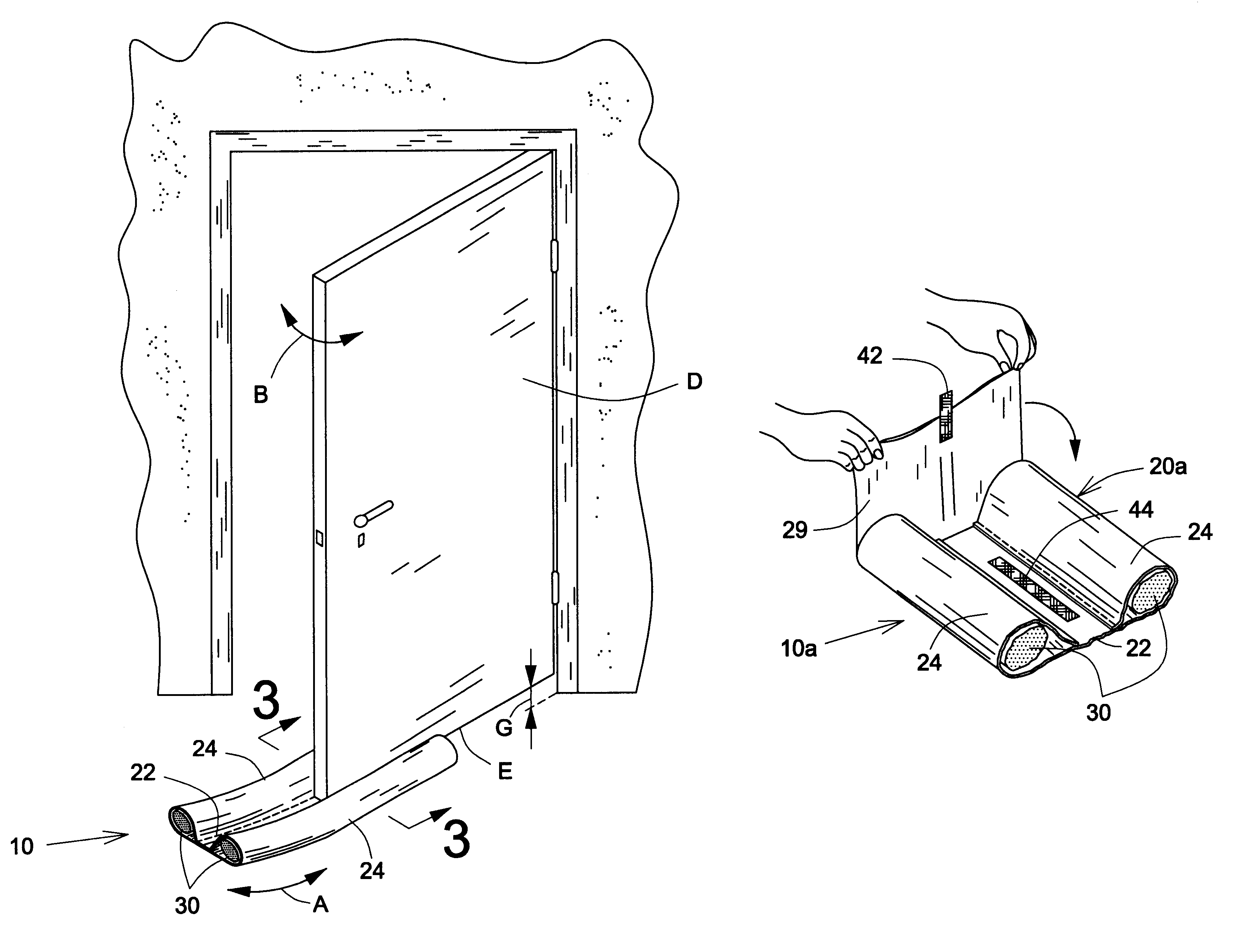
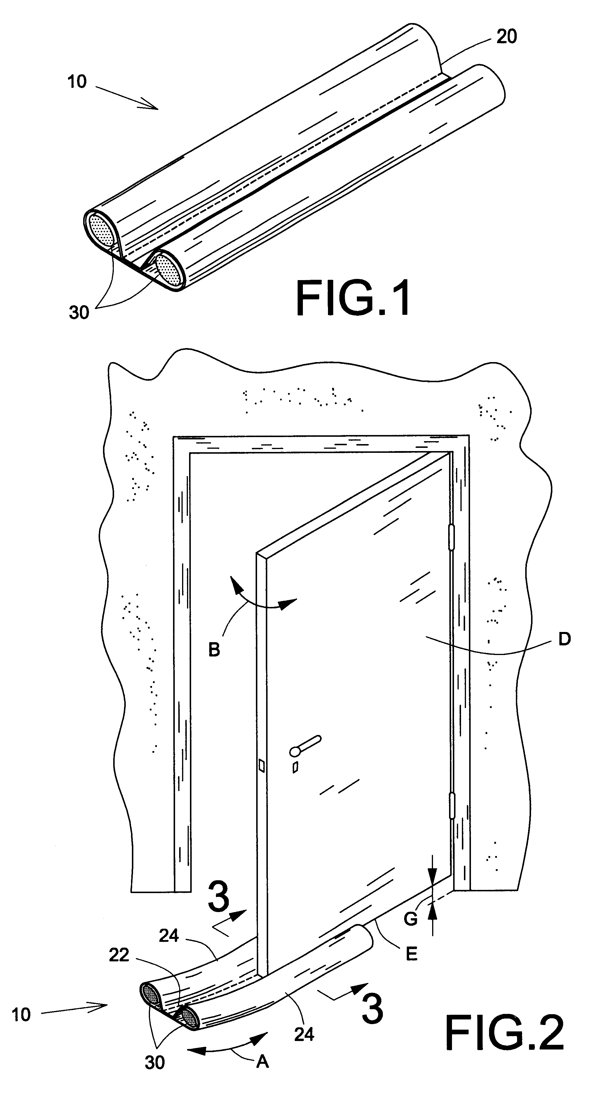
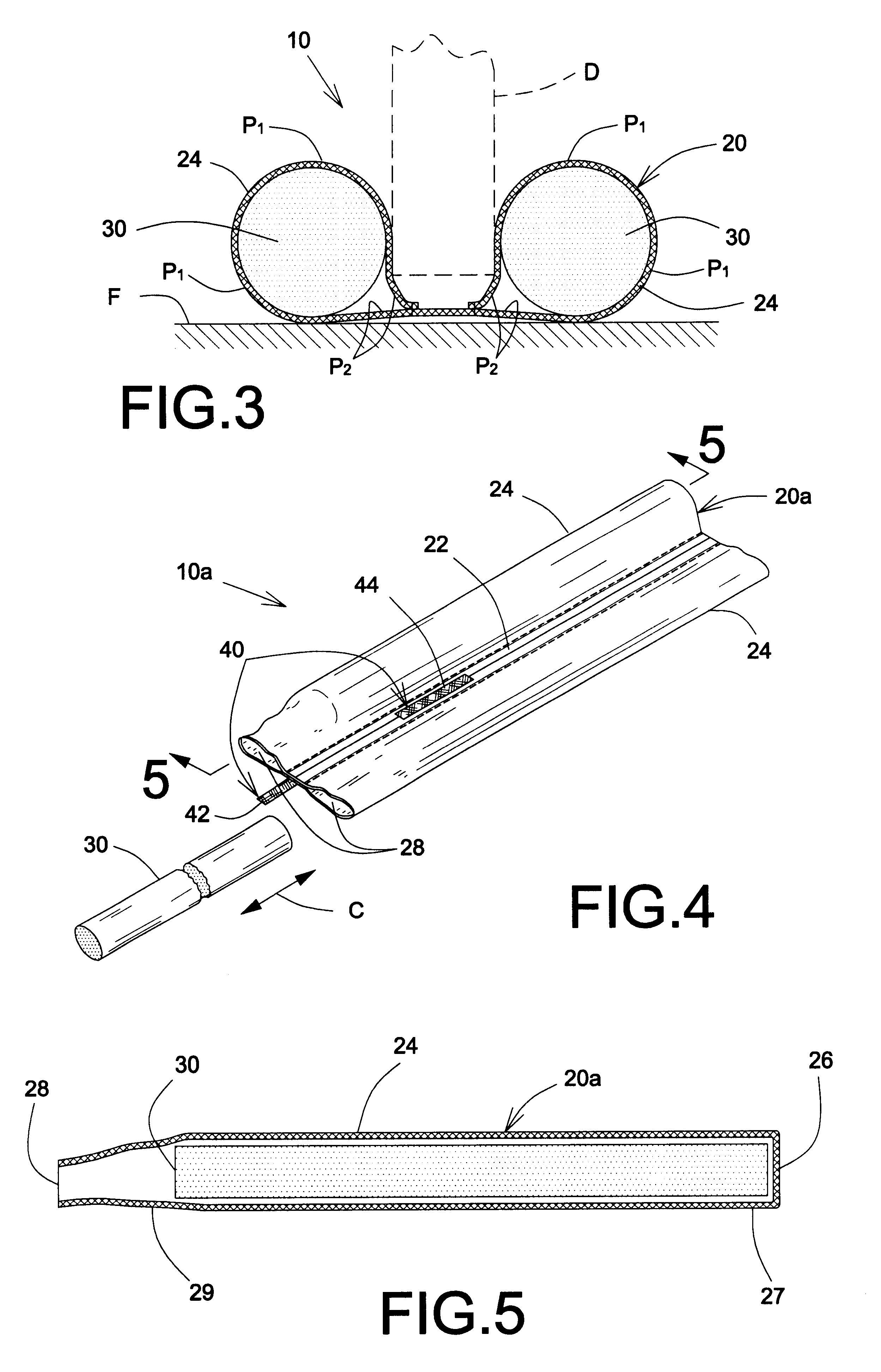
Referring to FIGS. 1 to 3 there is shown a first embodiment 10 of a removable draft excluder device according to the present invention which is adapted for substantially closed at least one side of an elongated gap G between a bottom surface E of a door D and a floor F therebeneath without being secured to the door D. The device 10 is sizable to fit different door D widths as draft guard and follows the door D along arrow B by sliding over the underlying floor F when the door D pivots around its mounting hinges (see FIG. 2).

The device 10 includes an elongated flexible body 20 used for substantially wrapping around the bottom surface E of the door D. The body 20 has a base section 22 that longitudinally extends through the gap G and joins two generally elongated sleeve members 24 integrally and laterally protruding from the base member 22 on opposite sides of the gap G adjacent opposite edges of the bottom surface E in a generally parallel and spaced apart relationship relative to ea...

Example

Referring to FIGS. 4 and 5, there is shown a second embodiment 10a of a removable draft excluder device according to the present invention in which each blocking member 30 fully engages its respective sleeve member 24. The latter has a closing 26 on a first end 27 of the body 20a and a free opening 28 on a second end 29, or foldable segment or retaining section, of the same 20a for receiving each blocking member 30 there through.

Accordingly, the body 20a is of a length slightly longer than the length of the blocking members 30 to enable to fold the second end 29 along a fold line located between the two ends 27, 29 towards the first end 27 for closing off the free opening 28 and to releasably secure or retain the blocking member 30 inserted therein against any axial displacement relative thereto (see FIGS. 5a and 5b). This folding essentially reduces the length of the body 20a down to the length of the blocking members 30 and the width of the door D.

As shown in FIGS. 4, 5a and 5b, t...


PUM

PropertyMeasurementUnit
Lengthaaaaaaaaaa
Widthaaaaaaaaaa
Impermeabilityaaaaaaaaaa

Abstract

A removable draft excluder for excluding drafts by sealing a gap between a bottom surface of a door and an underlying floor surface includes a first and a second sleeve, each having a generally elongated configuration for respectively receiving a first and a second blocking member, and a base section extending between the sleeves and maintaining the latter in a generally parallel and spaced apart relationship relative to each other. At least one of the sleeves defines longitudinally opposed sleeve first and second ends. One of the ends of the at least one sleeve is open and foldable about a fold line towards the other end of the at least one sleeve, which is closed, into a folded configuration so as to retain a respective one of the blocking members inside the sleeve between the sleeve ends. A fastening device releasably maintains the sleeve foldable end in the folded configuration.

Description

FIELD OF THE INVENTIONThe present invention relates to a seal device and, more particularly, to a removable draft exclude device for protecting against cold drafts or the like by creating a seal to close the gap between a door and its underlying floor.BACKGROUND OF THE INVENTIONThe need to create a thermal barrier at the base portion of doorway is a continuing pursuit in the construction industry. Various patents have been issued for devices that are directly attached to the door or the threshold base and act to inhibit the flow of cold or warm air, moisture or dust into the open space of the room.The early 1900 saw the evolution of a number of devices that essentially acted as rain guards. These were generally metallic in nature and required the installation of the device on the door, frame or both. U.S. Pat. No. 16,341 granted to Smith on Jan. 6, 1857, U.S. Pat. No. 641,139 granted to Ogan on Jan. 9, 1900, U.S. Pat. No. 924,434 granted to Cox on Jun. 8, 1909, U.S. Pat. No. 2,202,4...

Claims


Application Information

Patent Timeline
IPC IPC(8): E06B7/23E06B7/22
CPCE06B7/2316
Inventor HEROUX, STEVE
Owner HIP INNOVATIONS
Why Eureka
Try Eureka