

Hydraulic antivibration sleeve
- Summary
- Abstract
- Description
- Claims
- Application Information
AI Technical Summary
Benefits of technology
Problems solved by technology
Method used
Image

Examples
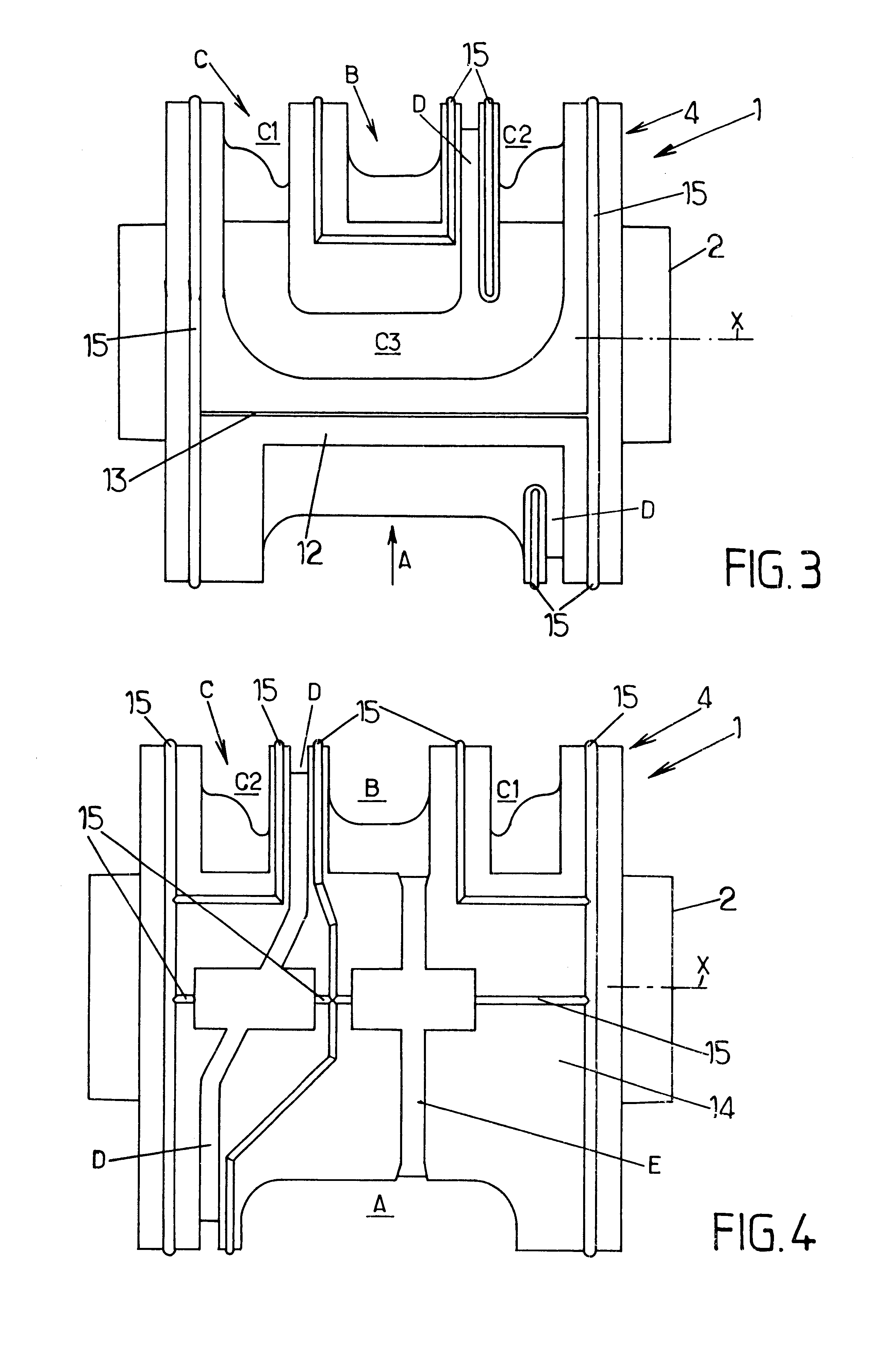
second embodiment
This second embodiment of the invention differs from the first embodiment in the following points:
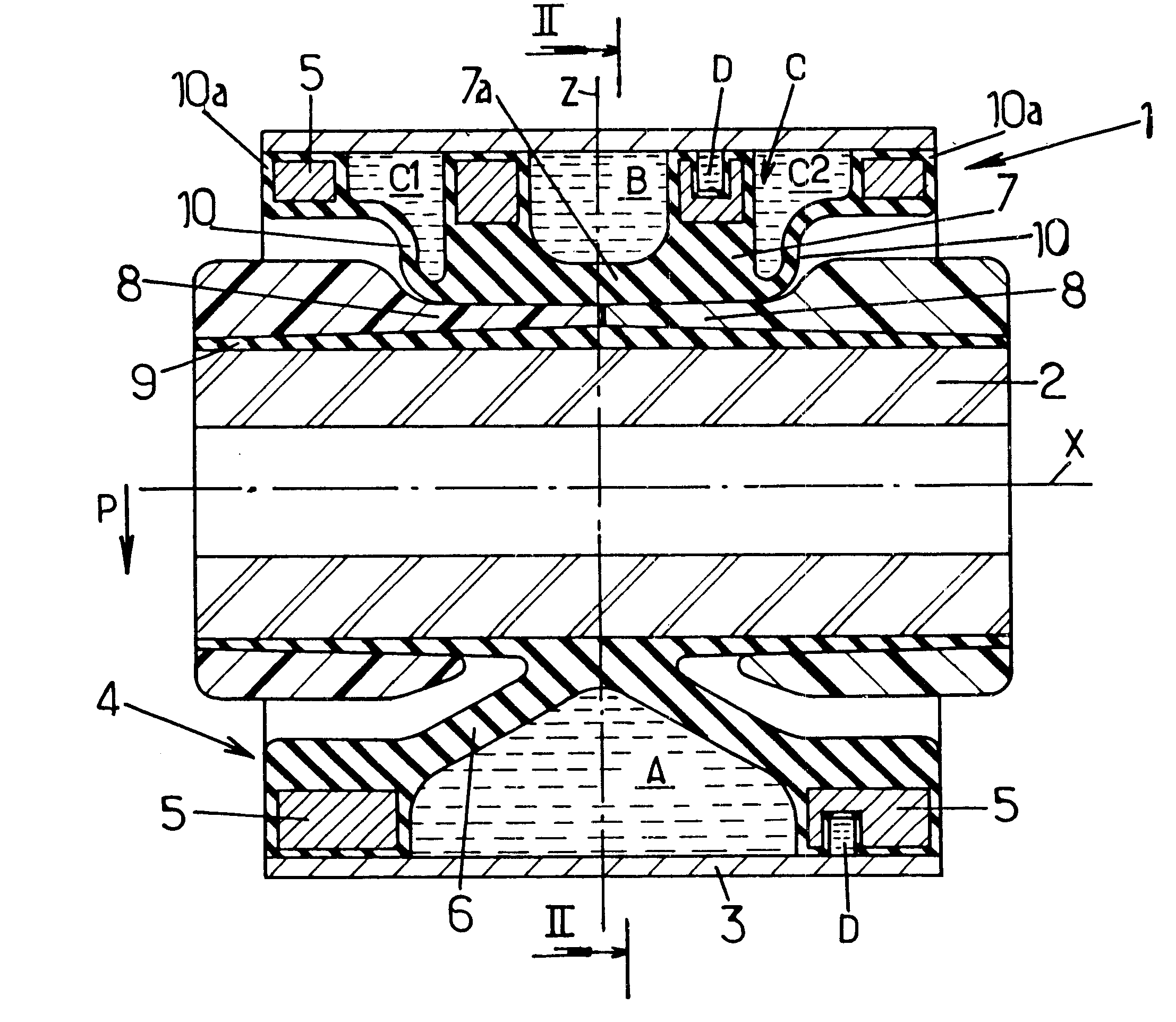
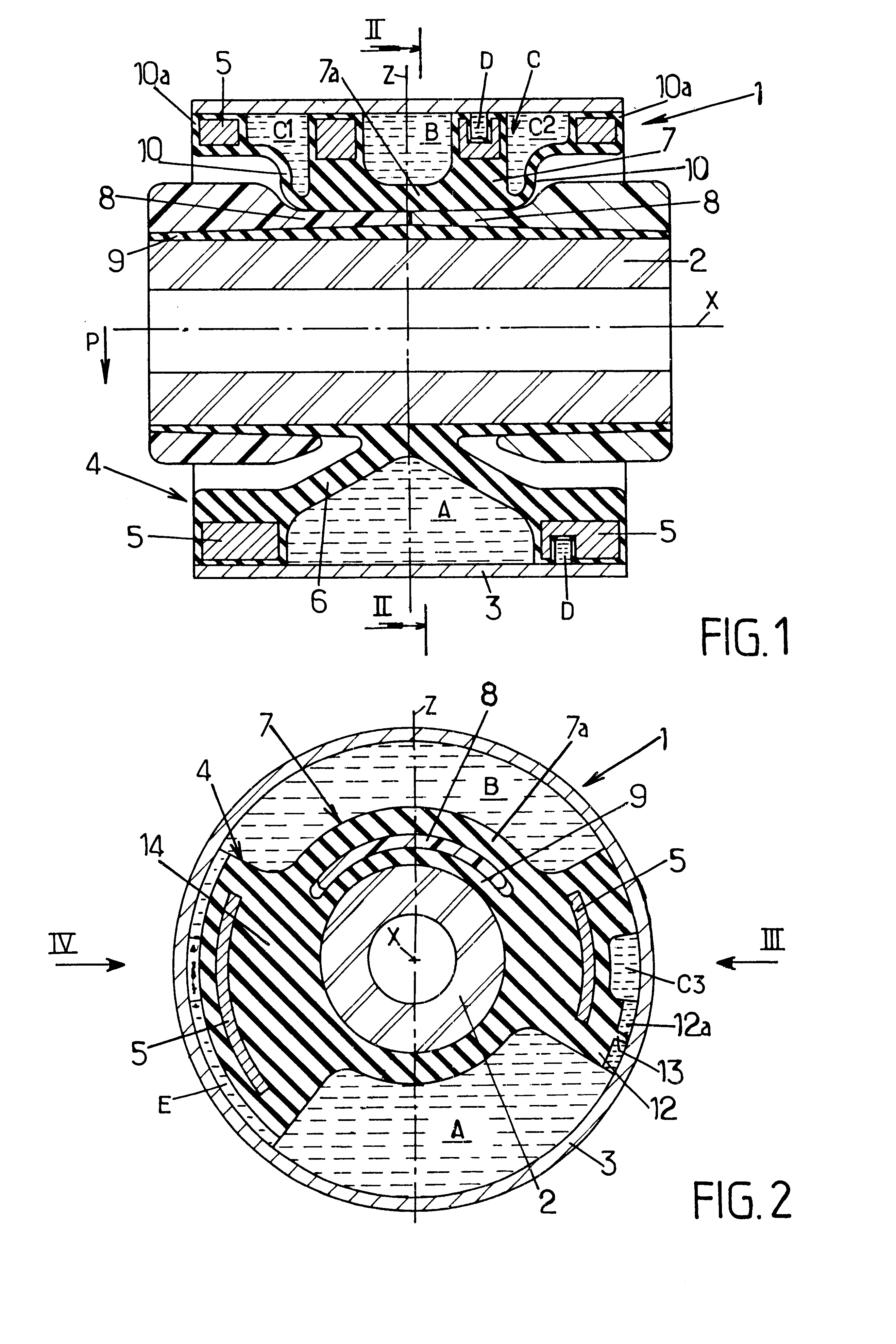
the flexible elastomer walls 17 are no longer integrally formed with the elastomer body 4 but are constituted by two elastomer annuluses fitted thereto so as to form bellows, each extending radially between an inner ring 18 bonded to the central layer 9 of the elastomer body and an outer ring 19 with rigid metal reinforcement 20 engaged as a force-fit in the outer strength member 3;
the side portions C1, C2 of the compensation chamber are annular and extend all around the inner strength member 2, thus lying adjacent to both working chambers A, B; and
the central portion C3 of the compensation chamber comprises the space that lies radially between the central portion 7a of the elastomer wall 7 and the central layer 9 of the elastomer body when said central portion 7a is no longer in contact with the inner strength member 2 of the sleeve.
PUM
 Abstract
Description
Claims
Application Information