Systems and methods for non-coplanar calibration of a scanning system

a scanning system and non-coplanar calibration technology, applied in the field of system and method for calibration of a document scanning system, can solve the problems of lamp fall-off, document scanning system periodic calibration, and calibration reference plane not being placed on the document plan

Inactive Publication Date: 2003-05-20
XEROX CORP
View PDF5 Cites 11 Cited by
  • Summary
  • Abstract
  • Description
  • Claims
  • Application Information

AI Technical Summary

Problems solved by technology

Due to instability in the scanning system illumination process, calibration of a document scanning system to a reference background is needed to obtain repeatable output.
However, document scanning systems need to be periodically calibrated because of drifts in lamp intensity and line voltage.
Due to size, shape, or other factors attributable to a scanning system, the calibration reference plane may be unable to be placed on the document plane, i.e., the platen glass.
In addition, a document scanning system that uses full le

Method used


Image

  • Systems and methods for non-coplanar calibration of a scanning system
  • Systems and methods for non-coplanar calibration of a scanning system
  • Systems and methods for non-coplanar calibration of a scanning system

Examples


Embodiment Construction

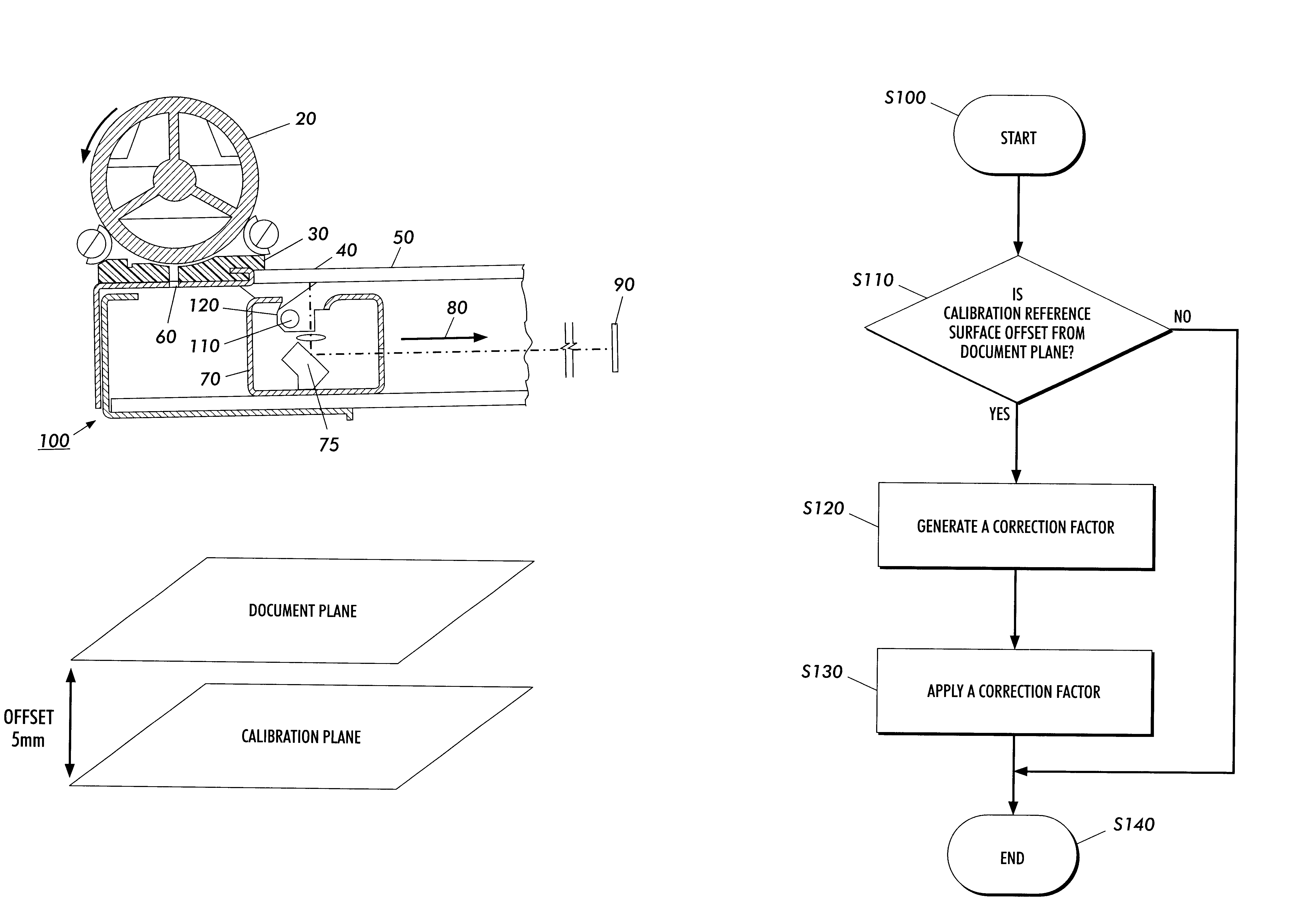
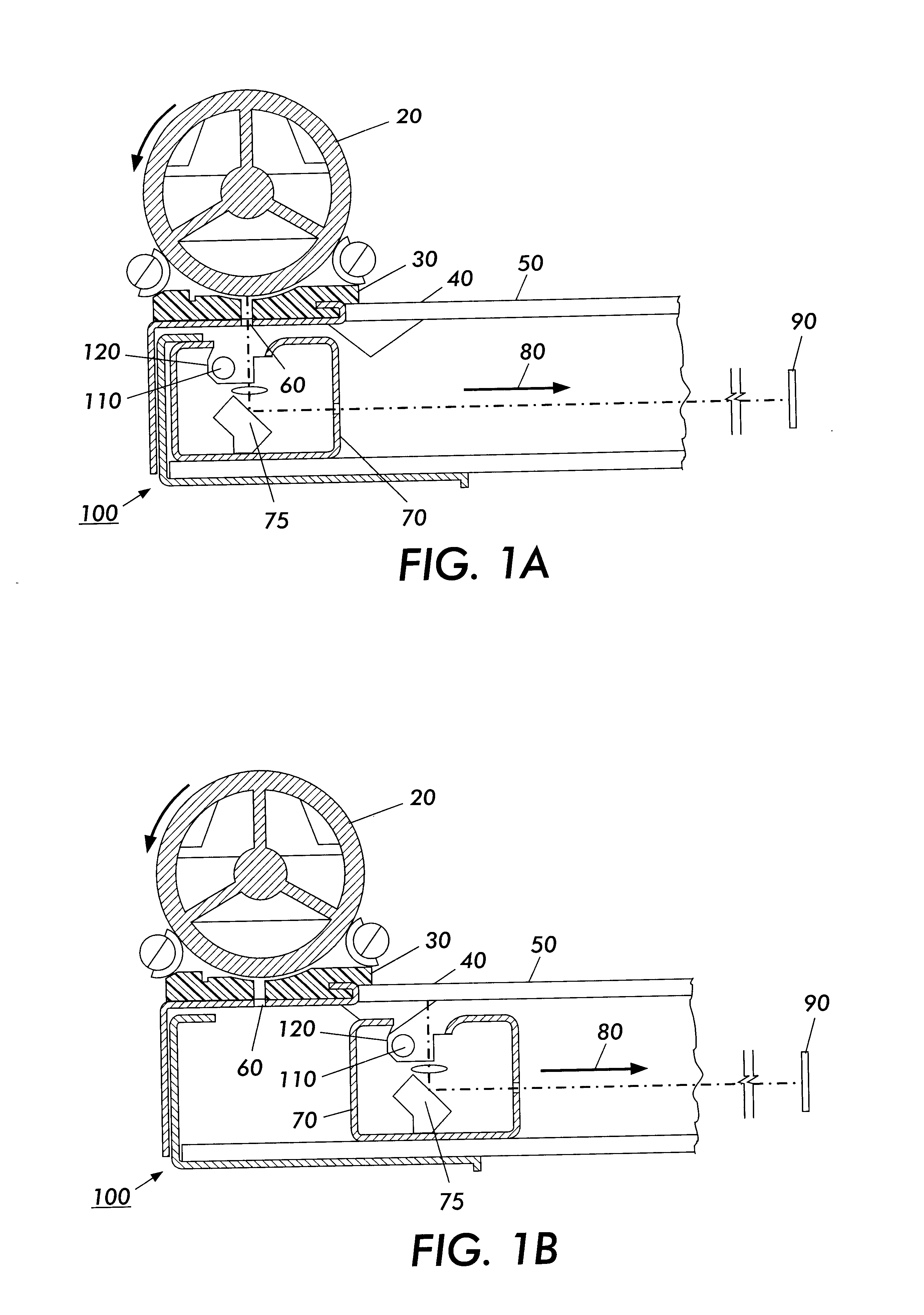
FIGS. 1a and 1b illustrate a diagram for an exemplary image data source 100 with a non-coplanar calibration system. In general, the image data source 100 is any one of a number of different sources, such as a scanner, a digital copier, a facsimile device, or any other known or later developed device that is suitable for generating electronic image data from a hard-copy or printed source. Further, the image data source 100 does not necessarily have to be a single device, but rather may be formed by two or more separate devices. FIGS. 1a and 1B apply to either a scanning CCD, i.e., linear array, or a fixed CCD array, respectively.

The image data source 100 in FIGS. 1a and 1b includes a constant velocity transport roll 20, a document registration edge 30 (DRE), a document plane 40, a calibration plane 50, a CVT glass 60, an imager scan carriage 70, a mirror 75, an imager scan direction 80, a lamp 110, a reflector 120, and a stationary imaging system 90. FIG. 1a shows a fixed illuminator...


PUM


Abstract

A non-coplanar calibration system exists when the calibration reference plane is offset from a document plane. Due to size, shape, or other factors attributable to a scanning system, it may not be feasible to place the calibration reference plane on the document plane, i.e., the platen glass. Lamp-fall off represents an effect that occurs as you get closer to the ends of the lamp and light energy is diminished. The profile difference between the calibration plane and the document plane in a non-coplanar system can be corrected for on a pixel by pixel basis. Illumination fall off due to the change in the distance from calibration plane to the document plane represents the main effect that must be corrected for. Also, the platen glass must be taken into account. A single calibration correction factor can be applied to each CCD element in a scanning system to account for the shift from calibration plane to document plane. Or a lumped parameter single calibration correction factor comprised of the average profile shift and the illumination shift can be used.

Description


Claims


Application Information

Patent Timeline
IPC IPC(8): H04N1/04H04N1/401H04N1/12H04N1/191H04N1/193H04N1/10
CPCH04N1/04H04N1/401H04N1/1017H04N1/1215H04N2201/0458H04N2201/044H04N1/193
Inventor THOMPSON, DAVID M.SAVAGE, ED C.HOWARD, JOHN I.
Owner XEROX CORP
Why Eureka
Try Eureka