Digital viscometer with arm and force sensor to measure torque

a torque measurement and viscometer technology, applied in the field of viscosity measurement, can solve the problems of prone to overload damage, relatively long response time of spring connection, and relatively high cost of converting deflection of spring to electronic signal

Inactive Publication Date: 2003-06-03
BI HONGFENG
View PDF19 Cites 23 Cited by
  • Summary
  • Abstract
  • Description
  • Claims
  • Application Information

AI Technical Summary

Problems solved by technology

However, it is relatively expensive to convert the deflection of the spring to electronic signal for automatic data acquisition and control purpose.
The drawback of this arrangement is that the response time of the spring connection is relatively long and the spring connection is prone to overload damage.

Method used


Image

  • Digital viscometer with arm and force sensor to measure torque
  • Digital viscometer with arm and force sensor to measure torque
  • Digital viscometer with arm and force sensor to measure torque

Examples


Embodiment Construction

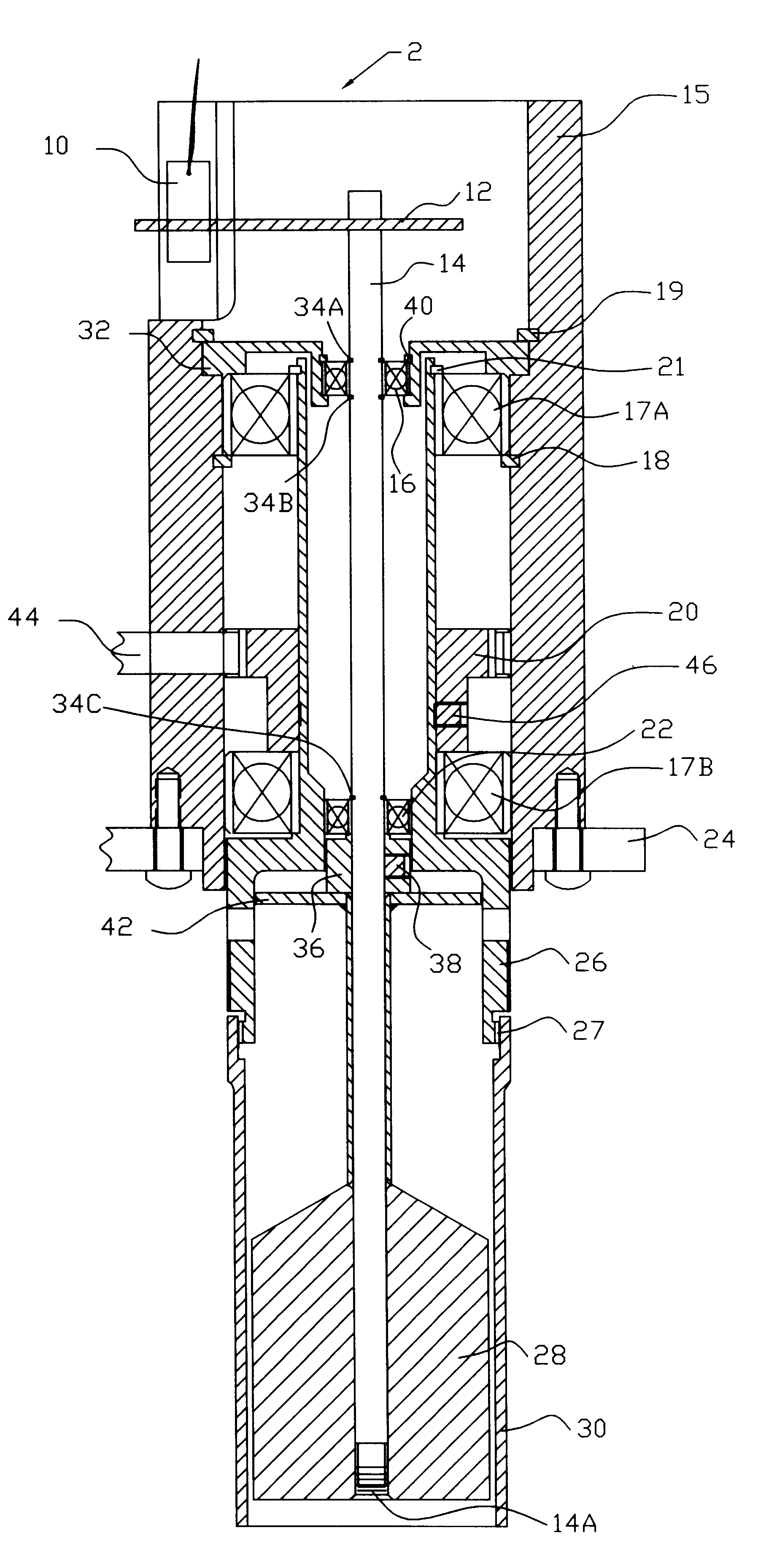
FIG. 1 shows a cross-view of viscometer 2 with a bob 28 and outside sleeve 30. The lower part of the sleeve can be opened for allowing the bob 28 and sleeve 30 to be immersed into a liquid--the liquid's viscosity to be measured. Sleeve 30 could also have a closed end to hold a small amount of to-be measured fluid. Sleeve 30 is detachable from rotor 26 via screw thread 27. Rotor 26 is mounted on main frame 15 through axially spaced bearing 17A, 17B with bearing retainer rings 18 and 21. Two spaced bearings 17A and 17B are needed for alignment. Sprocket 20 is pushed against bearing 17B and is secured to rotor 26 by set-in screw 46. Motor-driven timing belt 44 transmits the power to turn sprocket 20. Main Frame 15 and a motor are mounted to support plate 24.

Upper bearing retainer 32 pushes against bearing 17A and is locked to main frame 15 with snap ring 21. Shaft 14 is coaxially mounted respect to rotor 26 through axially spaced bearing 22 and 16 with bearing retainer rings 34A, 34B, ...


PUM

PropertyMeasurementUnit
viscosityaaaaaaaaaa
forceaaaaaaaaaa
mechanical dialaaaaaaaaaa

Abstract

Viscometer (2) with a sleeve (30) rotatable by a sprocket (20) and a timing belt (44) to shear a tested fluid thus imparting torque to a bob (28) mounted on a shaft (14) supported via axially spaced bearings (16, 22), an arm (12) connecting to the top of the shaft (14) applies force to a force sensor (10) which is proportional to the torque applied to the bob.

Description

Not applicable.1. Field of InventionThe present invention relates to measurement of viscosity with a variable speed drive and force-sensing device.2. Description of Prior ArtA liquid between two surfaces will shear when one surface moves relative to the other. The force needed to make such a movement is directly related to the viscosity of the liquid (with the mechanical configuration factored out). Viscometers typically rotate a cup or bob within a still cylinder with the liquid therebetween, or rotate an outer cylinder while keeping the inside coaxial bob inert. In such examples, torque is directly related to the viscosity of the liquid (again with mechanical configuration factored out).Several types of arrangement have been applied to measure the torque due to the viscosity of the liquid. In U.S. Pat. No. 3,435,666, a spring is attached to the inside bob while driving the outer cylinder. The mechanical dial reading reflects the deflection of the spring, which in turn is proportio...

Claims


Application Information

Patent Timeline
Patent Type & Authority Patents(United States)
IPC IPC(8): G01N11/10G01N11/14
CPCG01N11/14
Inventor BI, HONGFENG
Owner BI HONGFENG
Why Eureka
Try Eureka