
Low-section tire and mould and process for manufacturing a tire air tube

a technology of air tubes and low-section tires, which is applied in the field of air tubes for tires, can solve the problems of poor filling of the toroidal cavity, inability to leave the "tubeless" version in favour of the "tube type" version, and great difficulty in employing known rubber air tubes

Inactive Publication Date: 2003-06-03
PIRELLI TYRE SPA
View PDF19 Cites 12 Cited by
  • Summary
  • Abstract
  • Description
  • Claims
  • Application Information

AI Technical Summary

Benefits of technology

In a further aspect, the air tube of the invention is used as a vulcanization bladder, thus becoming one body with the tire carcass, in such a manner that it advantageously replaces the impermeable liner of tubeless tires.

Problems solved by technology

On the contrary, the solution of leaving the "tubeless" version in favour of the "tube type" version is not feasible with the so-called low-section tires, that is those having elliptical sections increasingly more elongated relative to the rotation axis, in which a great difficulty is found in employing known rubber air tubes.
Actually, traditional air tubes during inflation take a substantially circular profile in right section which badly matches with the elliptical tire profile, giving rise to folds overlapping each other that make it impossible to reach a correct and complete extension of the air tube walls over the inner surface of the toroidal cavity, in particular at the tire sidewalls, thereby generating a bad filling of the toroidal cavity and a dangerous state of inner stresses in the air tube wall, so that the air tube becomes quickly useless.
In conclusion, there is not yet the availability of an air tube adapted for being used with a low-section tire, which is capable of ensuring running under emergency conditions without being obliged to resort to an expensive and complicated modification of the tire carcass structure.

Method used


Image

  • Low-section tire and mould and process for manufacturing a tire air tube
  • Low-section tire and mould and process for manufacturing a tire air tube
  • Low-section tire and mould and process for manufacturing a tire air tube

Examples


Embodiment Construction

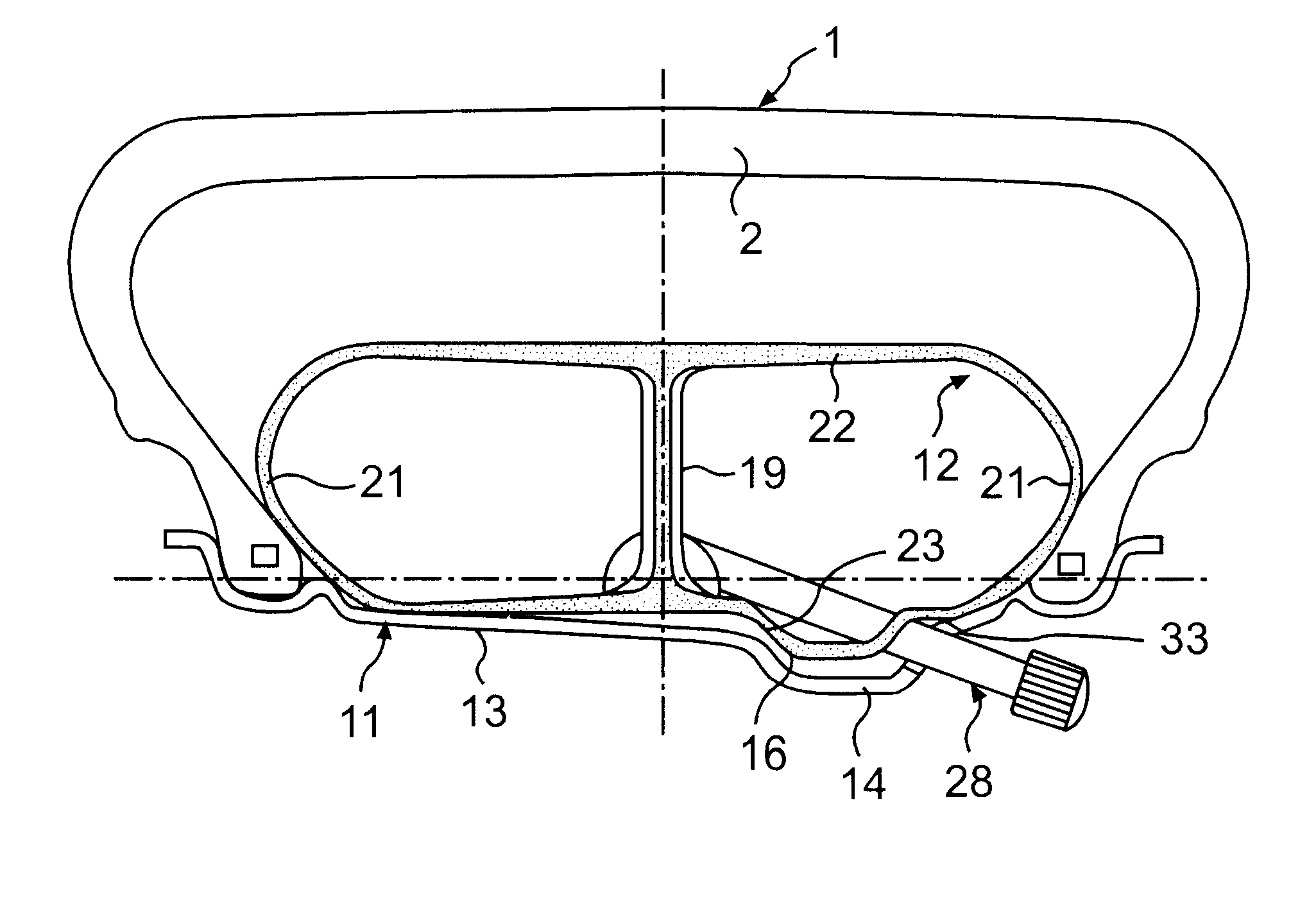
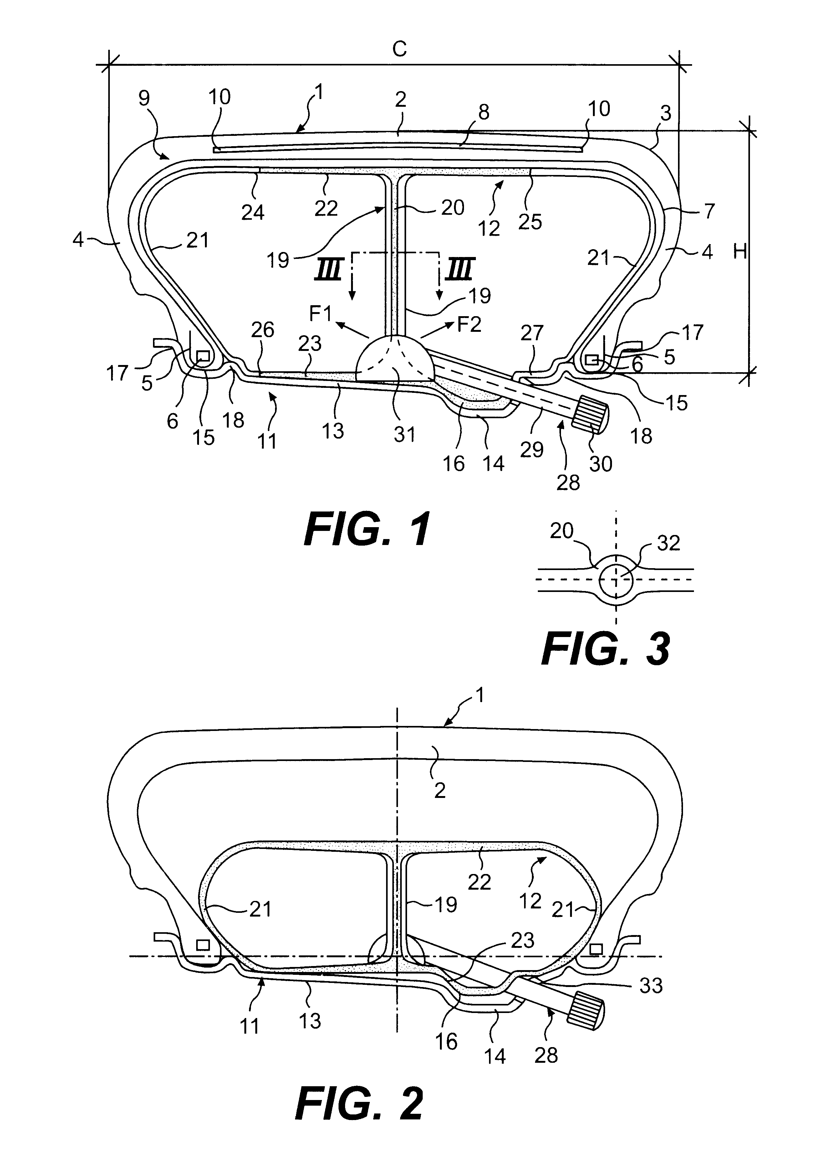
Shown in FIG. 1 is a radial-carcass tire identified by reference numeral 1. It comprises a tread 2, shoulders 3, sidewalls 4 and beads 5 incorporating bead rings 6. The carcass of tire 1 may comprise at least one ply 9 of rubberized fabric incorporating reinforcing cords 7 disposed in meridian planes.

In the example herein described the ply ends are turned up like a flipper around the bead rings 6: this does not exclude the possibility of other embodiments in which the carcass ply ends are anchored differently from the solution shown in FIG. 1, associated for example by adhesion with the axially inner sides of the bead rings without being turned up therearound.

A reinforcing belt structure 8, axially confined by its ends 10, is interposed crownwise to the tire, between the carcass ply and tread band.

Such a belt structure may for example comprise three radially superposed reinforcing layers (not shown), two of which are provided with metallic cords parallel to each other in each layer ...


PUM

PropertyMeasurementUnit
Fractionaaaaaaaaaa
Fractionaaaaaaaaaa
Fracture energyaaaaaaaaaa

Abstract

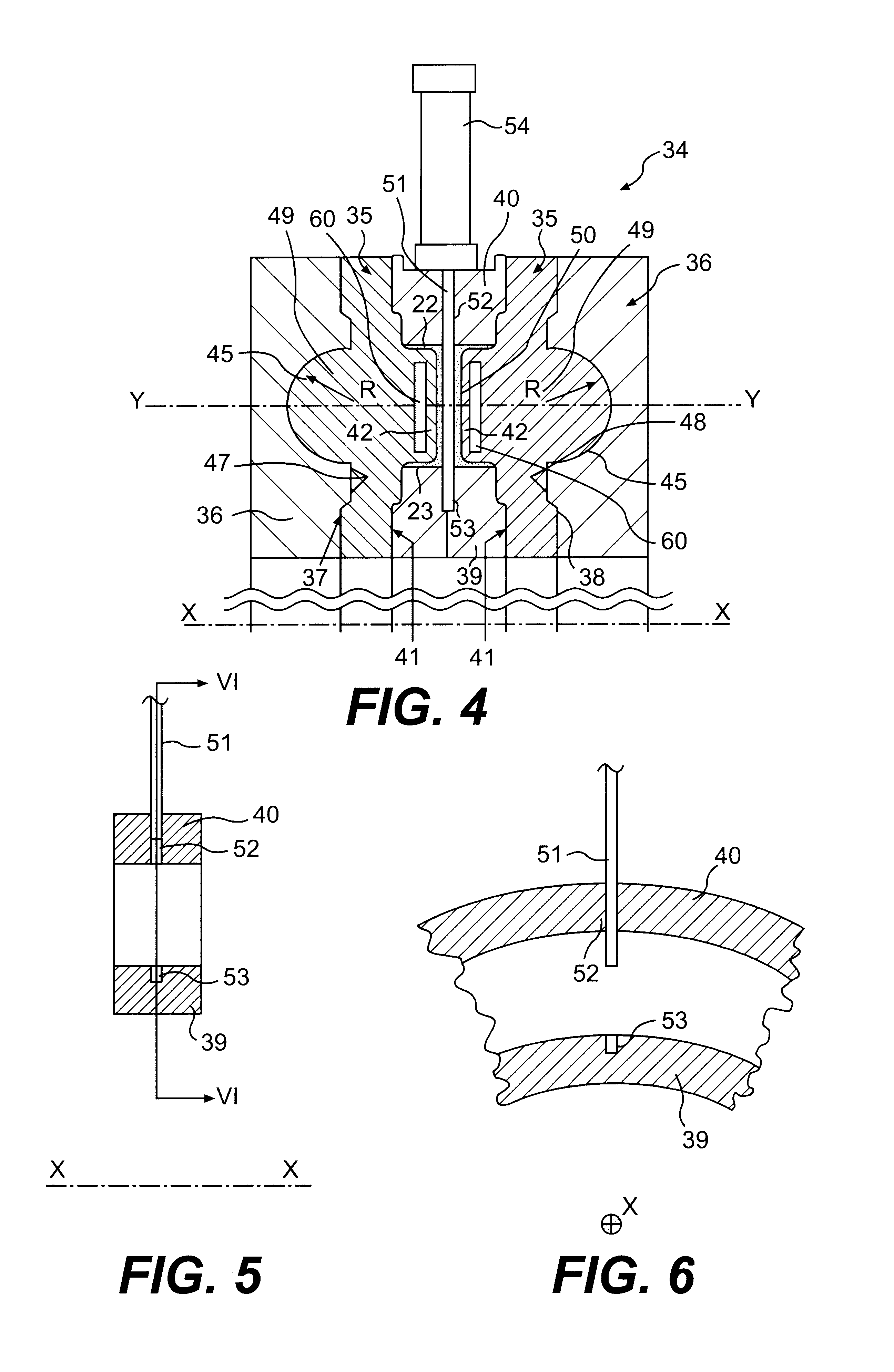
A low-section tire includes an air tube including an internal wall and two air tube sidewalls. The internal wall comprises a greater rigidity than the tube sidewalls so that, when a carcass and the tube are mounted on a rim, and during inflation, the tube sidewalls contact the carcass sidewalls no later than the internal wall contacts a crown portion of the carcass. A process for manufacturing the air tube includes moulding two tube sidewalls separated from each other, moulding a central core, arranging the tube sidewalls and central core in a single vulcanization mould, closing the vulcanization mould to form the tube, feeding pressurized fluid into at least two distinct circumferential portions of the tube, and vulcanizing the tube to join the central core and tube sidewalls. A mould for manufacturing the an air tube includes two axially-external cheeks, two axially-intermediate male dies, and two axially-inner spacers.

Description

1. Field of the InventionThe present invention relates to an air tube for tires, to a process and related apparatus for its manufacture, and to wheels comprising tires provided with such an air tube; more particularly, the invention relates to an air tube intended for supporting the tire even in case of deflation thereof, as a result of a puncture for example.More specifically, even if not exclusively, the air tube of the present invention is particularly suitable for tires of an elliptical transverse section in which the size of the minor axis parallel to the equatorial plane is smaller than the size of the major axis parallel to the rotation axis, and still more particularly for the so-called "low-section tires", in which the ratio of the section height measured between the bead base and the tread band centre to the maximum tire width is equal to or lower than 0.7.2. Description of Related ArtFor better understanding the terminology used in he progress of the present specification...

Claims


Application Information

Patent Timeline
IPC IPC(8): B29C45/00B60C5/22B60C5/04B60C5/08B60C5/00B29C33/02B29C35/00B29C35/02B29C65/00B29C69/00B29D23/24B29D30/06B29K21/00B29K105/24B60B21/02B60C5/20B60C15/00B60C15/02B60C15/05B60C15/06B60C17/00B60C17/01B60C17/02B60C19/00
CPCB29D23/24B60B21/023B60B21/028B60B21/104B60C5/04B60C5/08B60C5/22B60C15/0018B60C15/02B60C15/0236B60C15/05B60C15/06B60C17/01B60C19/001B29C45/006B29C35/00Y10T152/10612B29C65/00B29C2045/0072B29L2023/245B29L2031/601Y10T152/10522
Inventor CARETTA, RENATOMANCOSU, FEDERICO
Owner PIRELLI TYRE SPA
Learn More