Self-cleaning metering device

a self-cleaning and metering technology, applied in the direction of valve details, valve arrangements, valve members for absorbing fluid energy, etc., can solve the problems of hysteresis phenomenon, heterogeneity of injection flow rate, and all the greater friction, so as to reduce or even eliminate any build-up of contaminants. , to achieve the effect of reducing or even eliminating any build-up of contaminants

Inactive Publication Date: 2003-06-24
HISPANO SUIZA SA
View PDF12 Cites 44 Cited by
  • Summary
  • Abstract
  • Description
  • Claims
  • Application Information

AI Technical Summary

Benefits of technology

It is therefore an object of the present invention to alleviate these drawbacks by proposing a fluid metering device which makes it possible to appreciably reduce or even to eliminate any build-up of contaminants due to the movement of the fluid through the device.
With this particular structure, the fluid is compelled to sweep all the contacting surfaces. Self-cleaning of the device is thus ensured, thereby preventing the build-up of contaminants, and the creation of "gums", by discharging them with the metered fluid.

Problems solved by technology

It is known that in valves used for regulation, the operational guidance lengths give rise to friction which then generates a hysteresis phenomenon.
This friction is all the greater since the contamination which exists in any fluid causes the creation of "gums" on the contacting guiding surfaces.
In the particular case of the metering devices of fuel injection systems, in turbojets or turboprops (more generally referred to as turbomachines), this hysteresis causes a heterogeneity of the injection flowrate which could impair the proper operation of the turbomachine, especially at the time of switch-on thereof.
However, this solution has the major drawback of increasing the contact wear of the remaining operational surfaces and therefore of limiting the lifetime of the metering device.
However, here again, this solution proves to be inadequate when the build-up of gums or / and of contaminants becomes too large.

Method used


Image

  • Self-cleaning metering device
  • Self-cleaning metering device

Examples


Embodiment Construction

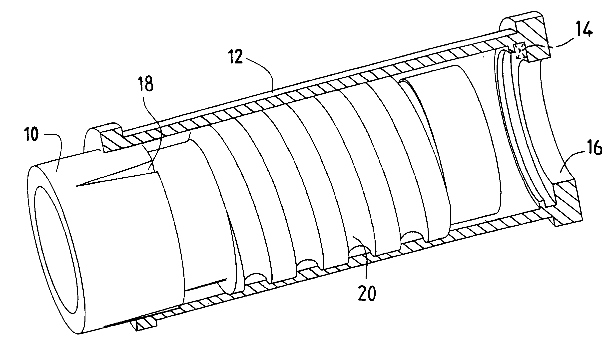
FIG. 1 illustrates in perspective a metering device in accordance with the invention, intended for supplying means of use (not represented) with a pressurized fluid fed from a supply source (not represented). An exemplary application of such a metering device is given with a system for injecting fuel into a combustion chamber of a turbomachine.

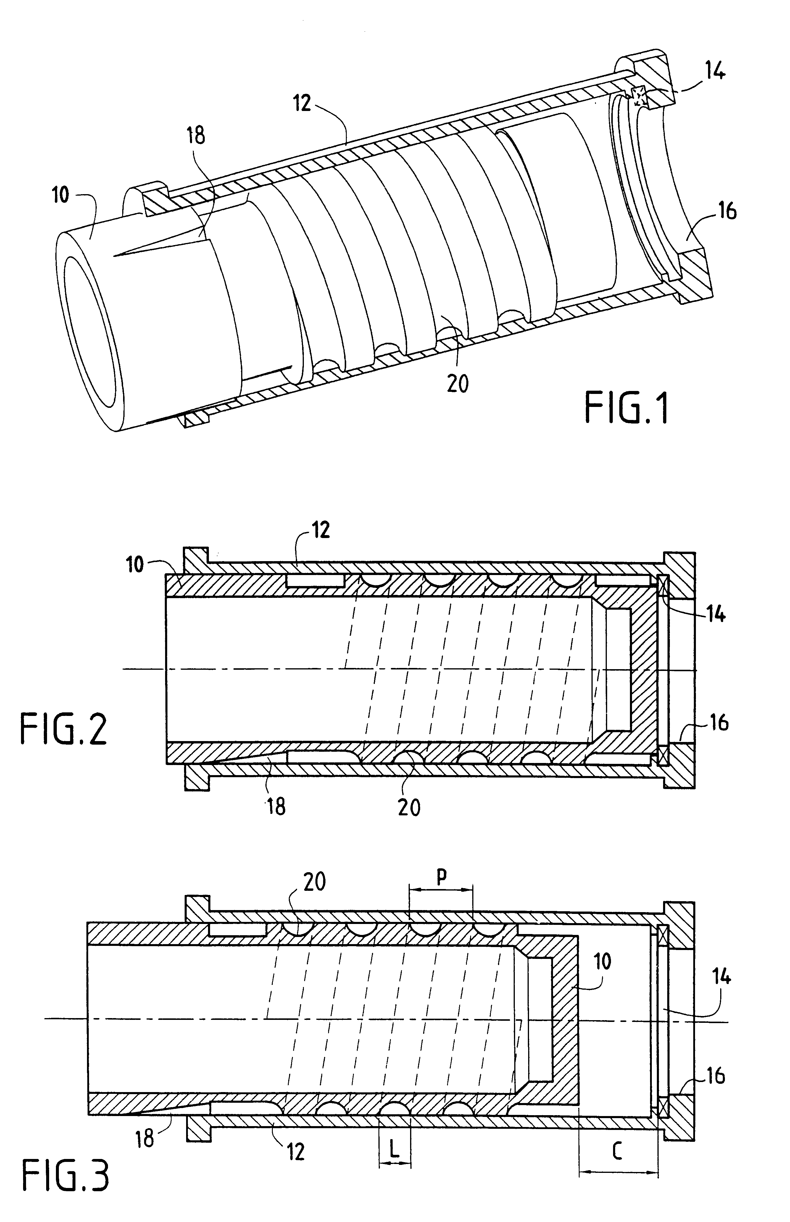
Under the action of the fluid subjected to a specified supply pressure, a metering valve 10 can slide in a cylindrical sleeve 12 between an initial closure position in which the valve blocks the fluid and comes into contact against a seal 14 disposed level with a fluid intake orifice 16 (see FIG. 2), and a terminal opening position in which the fluid can pass through the metering device and flow towards the means of use of this fluid through an ejection orifice 18 in the form of slots made in the metering valve and whose flow cross sections are dimensioned so as to ensure the desired metered dose at the level of these means of use (see FIG. 3)...


PUM


Abstract

In a fluid metering device for metering a fluid from a supply source to means of use of this fluid comprising a metering valve able to slide in a sleeve over a travel C, this valve comprising an intake orifice (16) for admitting the fluid from the said supply source and an orifice (18) for ejecting this fluid to the means of use, there are provided means (20) for channelling the fluid intended to allow, during the movement of the metering valve in its sleeve, a sweeping of the fluid over all the contacting surfaces of the valve and of the sleeve. The means of channelling the fluid advantageously comprise a helical groove of width L and of pitch P.

Description

The present invention relates to the general field of devices for controlling fluid flowrate and it is more particularly concerned with a self-cleaning metering device.PRIOR ARTIt is known that in valves used for regulation, the operational guidance lengths give rise to friction which then generates a hysteresis phenomenon. This friction is all the greater since the contamination which exists in any fluid causes the creation of "gums" on the contacting guiding surfaces.In the particular case of the metering devices of fuel injection systems, in turbojets or turboprops (more generally referred to as turbomachines), this hysteresis causes a heterogeneity of the injection flowrate which could impair the proper operation of the turbomachine, especially at the time of switch-on thereof.A solution to this problem conventionally consists in reducing the frictional surface areas. However, this solution has the major drawback of increasing the contact wear of the remaining operational surfac...

Claims


Application Information

Patent Timeline
Patent Type & Authority Patents(United States)
IPC IPC(8): F16K47/12F16K47/00
CPCF16K47/12
Inventor MICHAU, MARIONRODRIGUES, JOSETIEPEL, ALAIN
Owner HISPANO SUIZA SA
Why Eureka
Try Eureka