JTAG port-sharing device

a port-sharing device and port-sharing technology, applied in the direction of transmission, transmission monitoring, instruments, etc., can solve the problems of increasing the cost of integrated circuit board manufacturing, difficult testing of complex integrated circuits, interference in the functionality of integrated circuits,

Inactive Publication Date: 2003-06-24
LUCENT TECH INC +1
View PDF6 Cites 53 Cited by
  • Summary
  • Abstract
  • Description
  • Claims
  • Application Information

AI Technical Summary

Problems solved by technology

These complex integrated circuits are difficult to test.
Thus, the cost associated with the manufacturing of integrated circuits and circuit boards increases with the increased number of hardware pins.
This static causes interference in the functionality of

Method used


Image

  • JTAG port-sharing device
  • JTAG port-sharing device
  • JTAG port-sharing device

Examples


Embodiment Construction

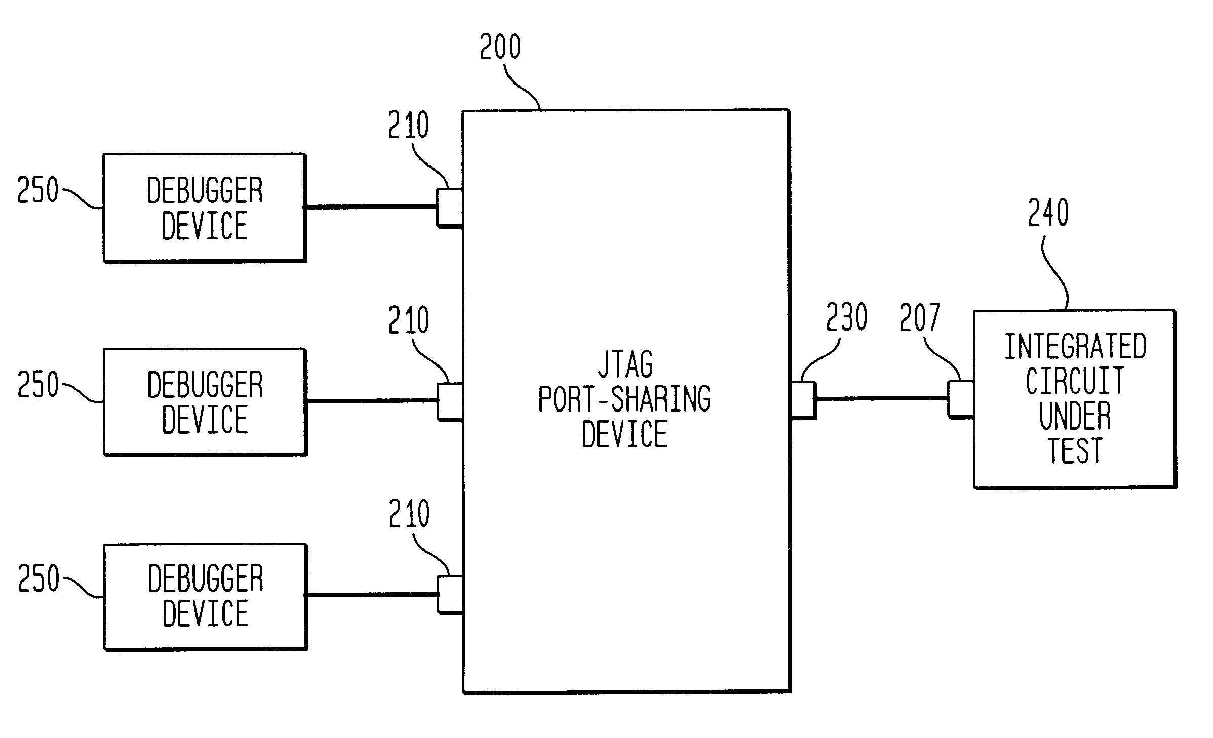
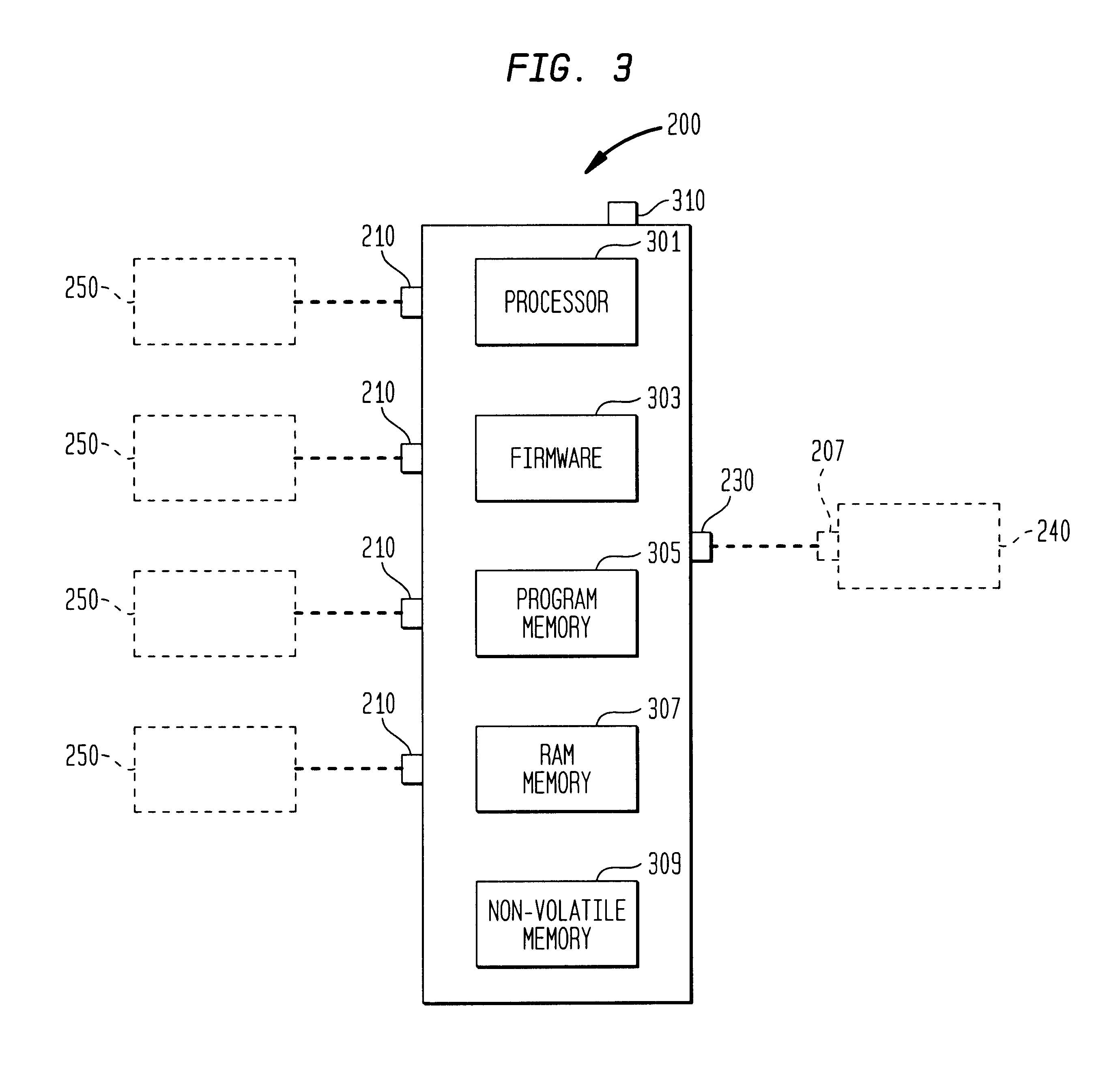
FIG. 2 is a block diagram illustrating various components of a JTAG port-sharing device 200 in accordance with one embodiment of the present invention.

JTAG port-sharing device 200 has two sides. The first side comprises a plurality of debugger ports 210 and is termed the debugger side. The second side has one common JTAG interface also known as an equipment-under-test (EUT) port 230 and is termed the chip side. Debugger ports 210 can be directly connected to a plurality of JTAG debugger devices 250 and the EUT port 230 can be connected to a JTAG test port 207 located on an integrated circuit under test 240. JTAG debugger devices 250 are capable of testing various functional blocks located on the integrated circuit under test 240.

Thus, JTAG port-sharing device 200 acts as a bi-directional interface between each JTAG debugger device 250 and a functional block located on an integrated circuit under test 240. JTAG port-sharing device 200 receives the test signals (or other control signa...


PUM


Abstract

A JTAG port-sharing device that reduces the required number of hardware pins on an integrated circuit without limiting the integrated circuit testing to a particular debugging platform is provided. The JTAG port-sharing device eliminates the need to have individual hardware pins for each functional block that requires JTAG test interface and allows one set of hardware pins to be shared by a plurality of functional blocks. The JTAG port-sharing device is not limited by a particular debugging platform and allows the use of pre-owned and/or off-the-shelf testing software and/or JTAG debugger devices thereby leading to shorter development cycles and lower development costs.

Description

1. Field of the InventionThe present invention relates to integrated circuit testing. In particular, the invention relates to use of a Joint Test Action Group (JTAG) interface in integrated circuit testing.2. Description of the Prior ArtThe use of various functional components (blocks) and component libraries to create complex integrated circuits is becoming increasingly common. These complex integrated circuits are difficult to test. Traditionally, these integrated circuits incorporate a JTAG test port as a mechanism for emulating and debugging an integrated circuit under test. The JTAG test port is used to download debugging or other testing software from an external device, e.g., a JTAG debugger device, to the functional blocks located on the integrated circuit under test. The JTAG test port is also used to upload the test results from the functional blocks to the JTAG debugger device. A JTAG (test port) standard has been adopted by the Institute of Electrical and Electronics Eng...

Claims


Application Information

Patent Timeline
IPC IPC(8): G01R31/28G01R31/3185
CPCG01R31/318555
Inventor BEAN, JOHN R.
Owner LUCENT TECH INC
Why Eureka
Try Eureka