Rotary cooling fan for an AC generator

a cooling fan and rotary technology, applied in the direction of liquid fuel engines, magnetic circuit rotating parts, magnetic circuit shapes/forms/construction, etc., can solve the problem of vehicle noise increase of alternative current generators

Inactive Publication Date: 2003-07-01
HITACHI LTD
View PDF23 Cites 27 Cited by
  • Summary
  • Abstract
  • Description
  • Claims
  • Application Information

AI Technical Summary

Problems solved by technology

As the high speed drive advances, there causes a problem in which the noises of the alternative current generator for vehicle increase.
However, the silence noise performance at the vehicle side (an engine except for the alternative current generator, auxiliary machineries, etc.) is advanced, a correspondence to the low noise performance by the alternation of the shape configuration by a thin plate press transforming fan according to the prior art reaches to the limitation.
Further, in the resin molding fan itself, it is difficult to obtain the full installation strength during the joining time to a back face of the core, however, in the resin molding fan having the insert metal fitting, in accordance with the insert metal fitting since the mechanical connection can be carried out by the welding etc. to the back face of the core, it is possible to ensure the installation strength similar to that of the press transforming product using the thin plate according to the prior art.

Method used


Image

  • Rotary cooling fan for an AC generator
  • Rotary cooling fan for an AC generator
  • Rotary cooling fan for an AC generator

Examples


embodiment 1

Carrying-Out Embodiment 1

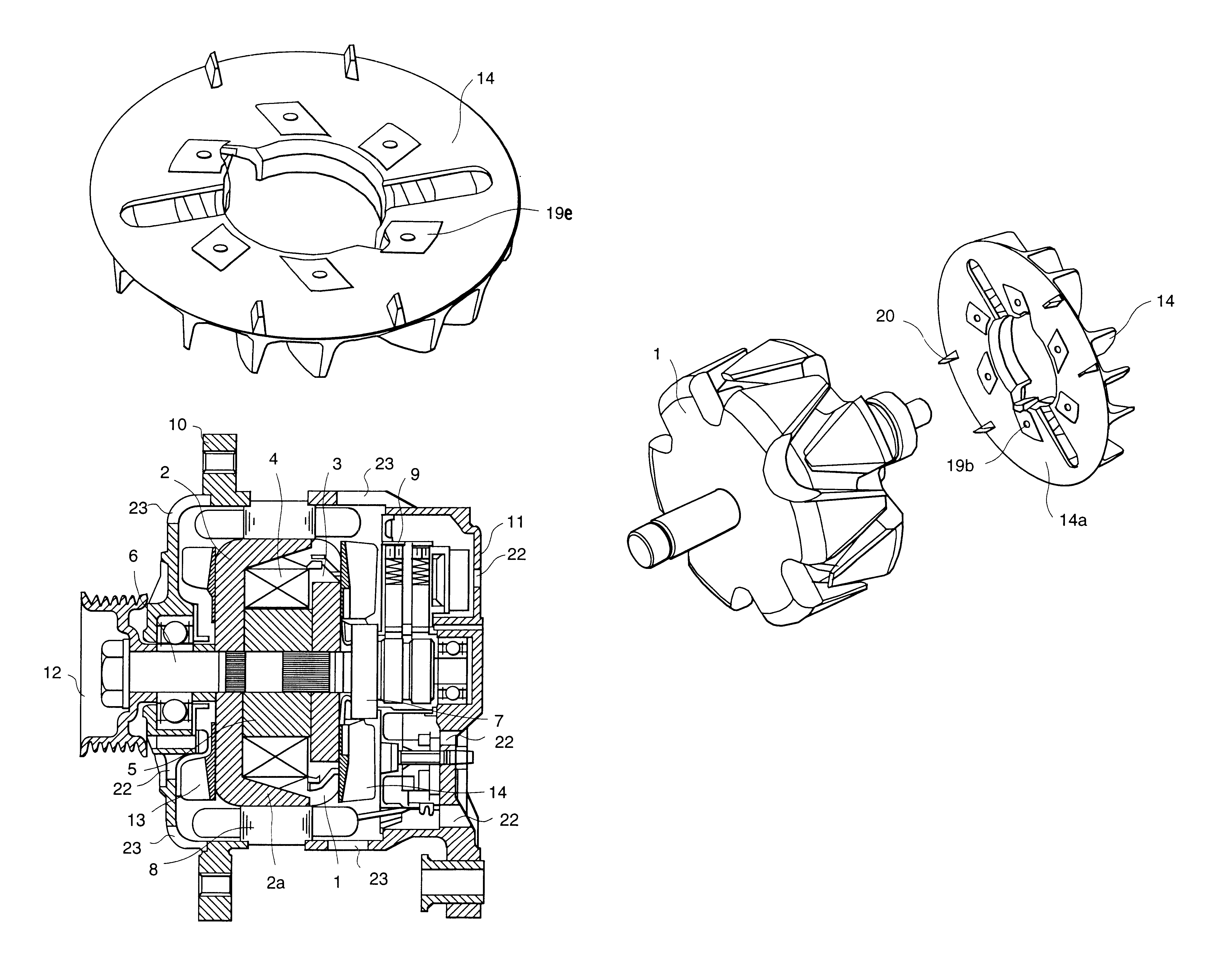
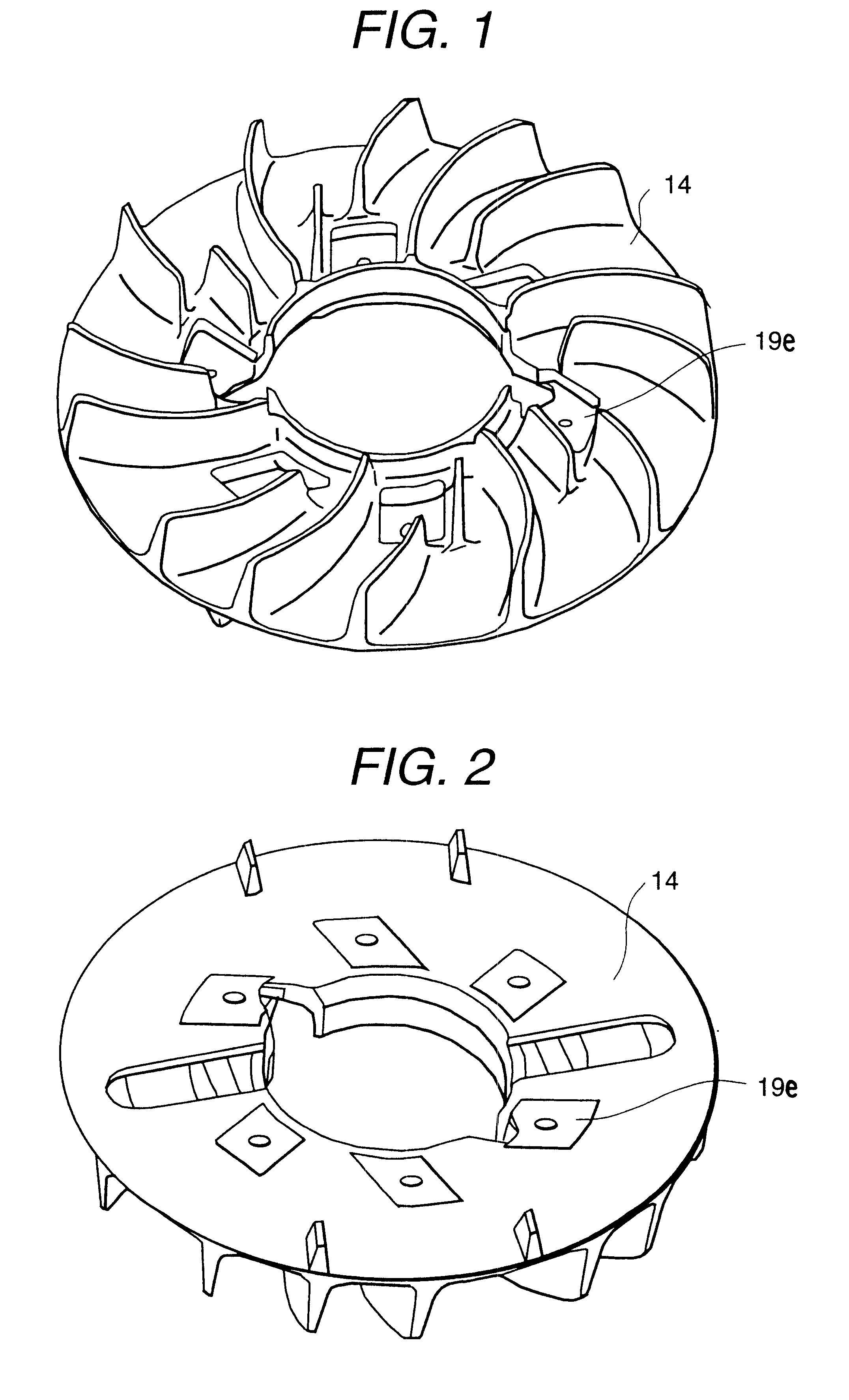
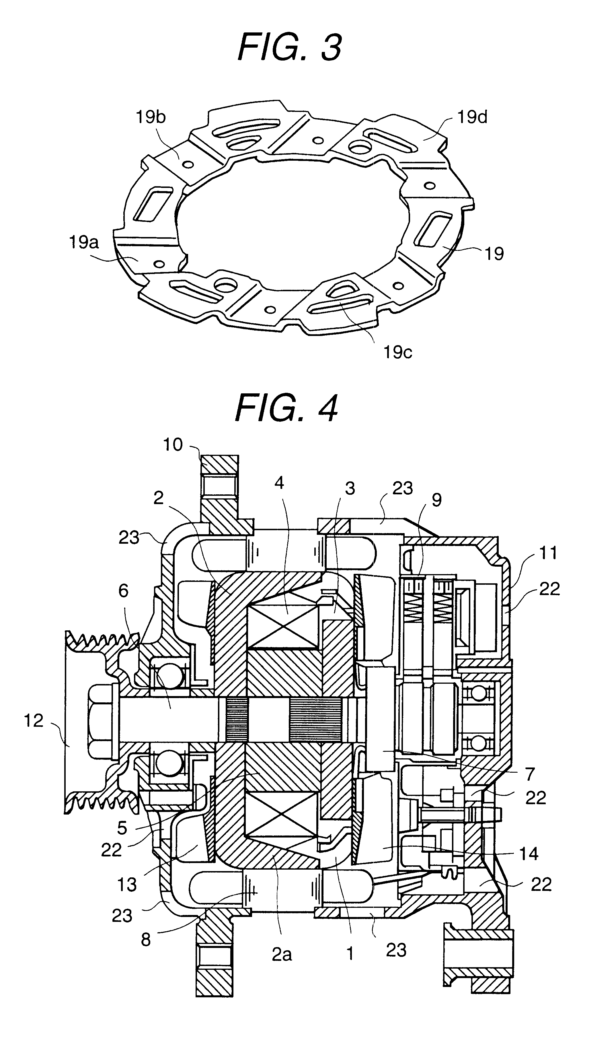
FIG. 1 and FIG. 2 are perspective views of a blade face of the rear fan 14 according to the present invention and a back face of the rear fan 14, and FIG. 3 is a perspective view of an insert metal fitting (an insert terminal) 19 according to the present invention which is molded integrally with the rear fan 14. In the respective views of FIG. 1, FIG. 2 and FIG. 3, the rear fan 14 is made of a resin product in which the insert metal fitting 19 is molded integrally. The insert metal fitting 19 is molded by molding an iron plate having SPCCt=1.2 degree using a press process.

To a flat face portion 19a of the insert metal fitting 19, plural welding portions 19b which project in an opposed side of the core 2 are provided in a peripheral direction. Further, the insert metal fitting 19 is not a mere flat plate but the insert metal fitting 19 itself is molded on an even and uneven face, and to an outer peripheral portion plural empty holes 19c or raised portions 19d...

embodiment 2

Carrying-Out Embodiment 2

FIG. 5 is a detailed cross-sectional view showing an installation condition of the fan to which the alternative current generator for vehicle of the Carrying-Out Embodiment 2 according to the present invention is applied. As to the procedure of the installation of the rear fan 14 to the core 2, the rear fan 14 is contacted to a back face of the core 2, and after positioning, in the welding portions 19e the welding is carried out and then the fan is fixed. In FIG. 5, a resin portion inner diameter size .alpha..sub.i of the resin mold rear fan 14 in which the insert metal fitting 19 is molded integrally is established to have the substantial same diameter of a resin portion inner diameter size .beta..sub.1 of the slip ring 7.

Accordingly, according to the Carrying-Out Embodiment 2 of the present invention, it is unnecessary to carry out the positioning of the fan 14 during the axial center installation of the fan 14 to the back face of the core 2 against the co...

embodiment 3

Carrying-Out Embodiment 3

FIG. 6 is a perspective view showing a before condition for installing the fan which is applied to the alternative current generator for vehicle of the Carrying-Out Embodiment 3 according to the present invention to the core, and FIG. 7 is a view showing an installation condition of the fan in the alternative current generator for vehicle of the Carrying-out Embodiment 3 according to the present invention.

In FIG. 6, in a rear face portion 14a of the projecting face of the blade of the rear fan 14, a total four portions, namely one side two portions, of trapezoid shape configuration positioning use raised portions 20 which are suited to the back face portion shape configuration of the core 2 are provided. Since an interval .alpha..sub.2 of the positioning use raised portions 20 is established to have a minute gap degree to a width .beta..sub.2 of the back face of the core 2, during the installation time of the fan 14 to the core 2 the positioning of the rear ...


PUM


Abstract

Since a structure of a cooling fan of an alternative current generator for a vehicle is formed with a resin molding product having an insert metal fitting, a freedom degree on said fan design shape configuration and said installation performance of said fan to a core can be compatible. A cooling fan structure having a high shape configuration design freedom degree and having an installation strength similar to that of said fan according to said prior art can be obtained.

Description

1. <Technical Field>The present invention relates to a vehicle AC generator or an alternative current generator for a vehicle and in particularly to a ventilation cooling fan of an alternative current generator for vehicle and a manufacturing method of the same.2. <Prior Art>FIG. 9 is a cross-sectional view showing a construction of an alternative current generator for vehicle according to the prior art. A rotor 1 is constituted by a bobbin 3 to which a field coil 4 is wound, a yoke 5 for forming a magnetic iron core, a pair of cores 2 comprised of plural claw shape configuration portion chips (plates), a front fan 15 and a rear fan 14 which are welded and fixed to an end face of the core 2, a rotating shaft 6, and a slip ring 7. The pair of cores 2 sandwiches the bobbin 3 to which the field coil 4 is wound and the yoke 5 and claws 2a are arranged to mesh, and the cores 2 are inserted and fixed to a substantial center portion of the rotating shaft 6.To an outer periphera...

Claims


Application Information

Patent Timeline
Patent Type & Authority Patents(United States)
IPC IPC(8): F04D29/28H02K9/06H02K9/04H02K19/22
CPCF04D29/281H02K9/06
Inventor ISHIDA, SAKAESASAKI, SUSUMUHONDA, YOSHIAKI
Owner HITACHI LTD
Why Eureka
Try Eureka