The modern forms of such emergency running systems, which have already been under discussion for decades, e.g., emergency running support elements mounted on the rim, or sidewall-reinforced tires, combined with today's customary vehicle and suspension comfort, have the general
disadvantage that an emergency running condition is no longer noticed by the driver as a result of the behavior of the vehicle being markedly different from the normal condition, so that there is a danger that the emergency running ability which, as a rule, is limited with respect to time or distance driven, is overtaxed and can finally result in the total failure of a tire or wheel, which then can again be extremely hazardous to the vehicle and its occupants.
The
disadvantage of such mechanical / acoustic warning devices is essentially that in today's customary excellent damping and decoupling between the
chassis and the bodywork in connection with a desired high level of suspension and driving comfort and good sound insulation of the interior of the vehicle, the resulting noises or vibrations are no longer reliably detected by the driver, or else would have to be so loud or severe that it would simply not be possible to continue driving.
While it is true that a direct measurement of air pressure, for example, via aneroid boxes inside the tire, represents a reliable detection method, it results in a high expenditure on sensing, power supply, and transmission systems by which the changes in air pressure measured inside the rotating tire can be transmitted to the stationary sensors installed in the vehicle and thus to the
processing electronics.
The device conceived here for the large-scale mounting conditions of a
truck tire requires a high expenditure on additional components that make the entire
system more expensive, is extremely high-maintenance and susceptible to mechanical damage and soiling, makes it difficult to change the tire, and also, because it is necessary to arrange the system on all tires, represents a system that calls into question cost-effective production, even in
series production and, in particular, for passenger automobile tires, owing to its high level of complexity for sensors, cabling, and other additional components.
On the other hand, pressure loss warning systems based on the detection of the dynamic rolling circumference, have a number of imponderabilities that lead to inaccurate measurements or decisions.
The disadvantages and difficulties associated with all these methods and devices in detecting and reliably reporting a pressure loss are clear if it is recalled that the changes in the dynamic rolling circumference can be severely influenced by a number of different parameters.
Thus, the problem of measurement techniques to sense these different influence variables and their electronic processing to produce a reliable signal has not yet been solved satisfactorily and is decidedly difficult.
A farther great uncertainty in measurements for determining air pressure based only on the current rolling circumference arises because the influence of inflation pressure and speed on the rolling circumference for tires of various makes or differing construction is very different.
The absolute value of the rolling circumference is therefore relatively unsuited for a warning.
Also, the difference between the rolling circumferences of all tires on a vehicle does not lead to reliable information, since, e.g., different degrees of wear or the mounting of new tires cannot be recognized or else a slow loss of air pressure on two or more tires cannot be ascertained.
To compensate for such imponderabilities, a new calibration would have to be performed constantly, also independently of the distance traveled, which would make the system more expensive and render the operation relatively unsafe, since a new calibration during the journey would naturally have to be performed by the driver of the vehicle.
These methods or devices also have the
disadvantage that there is no typical vibration or oscillation behavior in emergency running and it is therefore difficult to determine and detect since, even in emergency running, the different tire construction, nature of the
road surface, speed, and various acceleration or braking procedures cause such a strong
superimposition or influence that it is scarcely possible to differentiate clearly between disturbances and emergency running.
Thus additional emergency running support elements become unnecessary, although with the slight disadvantage that the tires as such are heavier, so that the choice of embodiment to be used must be tailored to the individual case.
Furthermore, the same effect is also achieved in that the
periodic oscillations that are characteristic of the emergency running condition and in proportion to the wheel rotation speed are produced by a number of discontinuities distributed non-uniformly over the circumference.
However, with such a processing method of the speed output signal, it must be taken into consideration that, in evaluating the number of single pulses obtained within a defined count time T.sub.L, bodywork or structural oscillations or resonances can influence and change the
evaluation result, without necessarily making it considerably less informative.
Their detection by appropriate sensors in fact requires more complex design and their electronic processing leads to a considerably more complicated structure in the
electronics, which thus becomes unnecessary.
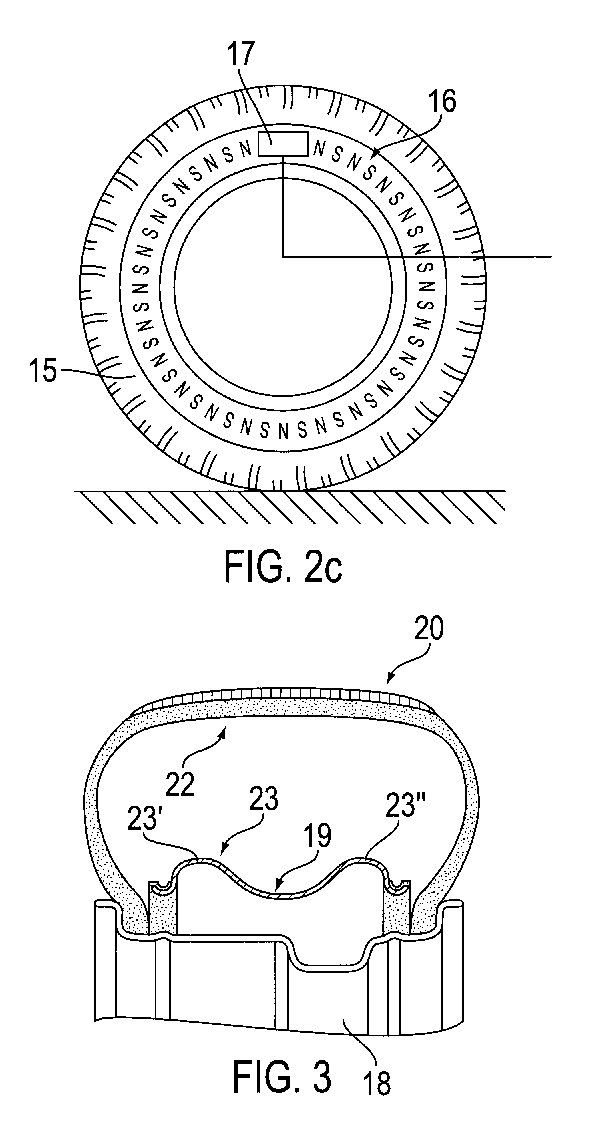
This makes it possible to obtain a defined emergency running signal even when no separate emergency running support elements are provided inside the tire, but nevertheless the tire is designed so that its shape remains stable in the emergency running condition, with the result that a limited
continuation of the journey is possible and simultaneously a reliable signal is detectable for the recognition of this condition.

