
Driver control module

a technology of control module and driver, which is applied in the direction of mechanical control devices, instruments, roofs, etc., can solve the problems of considerable extra effort and labor

Inactive Publication Date: 2003-07-15
INT TRUCK INTPROP LLC
View PDF20 Cites 35 Cited by
  • Summary
  • Abstract
  • Description
  • Claims
  • Application Information

AI Technical Summary

Benefits of technology

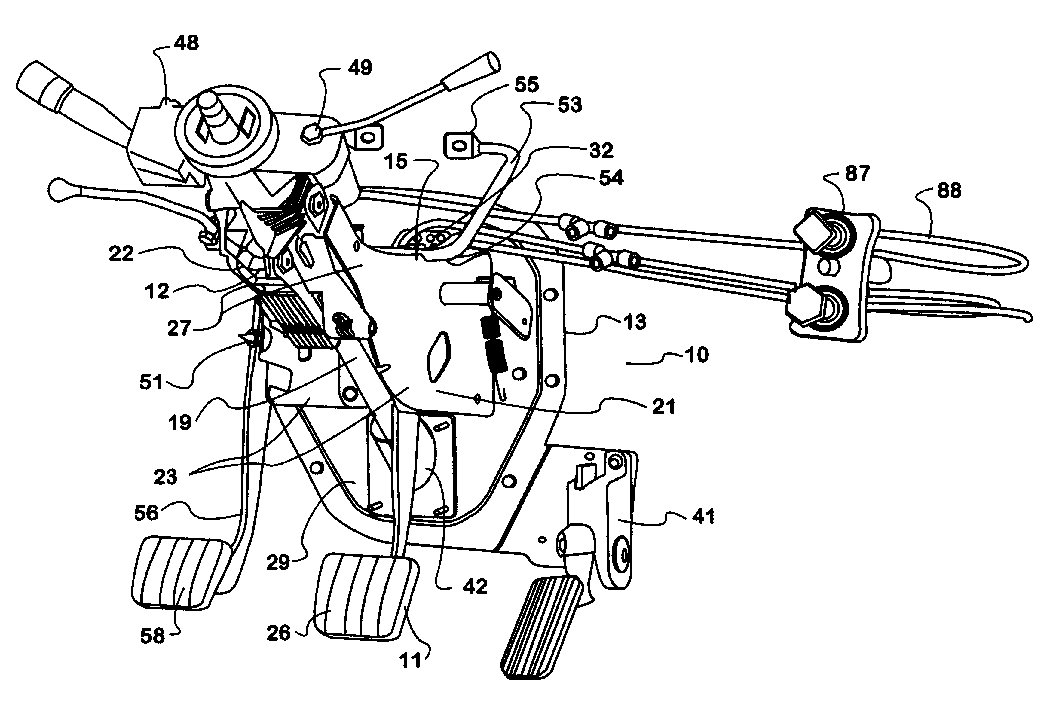
There are parallel steering column engagement arms engaged to the vertical-mounting surfaces. The steering column is mounted to and between the column engagement arms. The steering column contains at least one engagement means on each side for engagement to each column engagement arm. The steering column is long enough to pass through the dash engagement piece. When installed, the steering column is then engaged to an intermediate steering piece that is then engaged to a steering gear. The steering column is engaged to a through wall bushing at the engagement piece. The steering column may have a turn signal module integrated to it. Additionally, for trailer pulling vehicles, the steering module may have the trailer hand control integrated. Integration into the DCM will allow installation of these components separate from the main assembly line thereby saving time. The DCM steering column may also use a clock spring to ensure continuity of electricity to the collision event initiated driver air bag.

Problems solved by technology

This involved considerable extra effort and labor.
Additionally, there is hole for a fill-in gland that allows passage of the air tubing from the brake valves and the push-pull double check valve and other cab operated air valves.

Method used


Image

  • Driver control module
  • Driver control module
  • Driver control module

Examples


Embodiment Construction

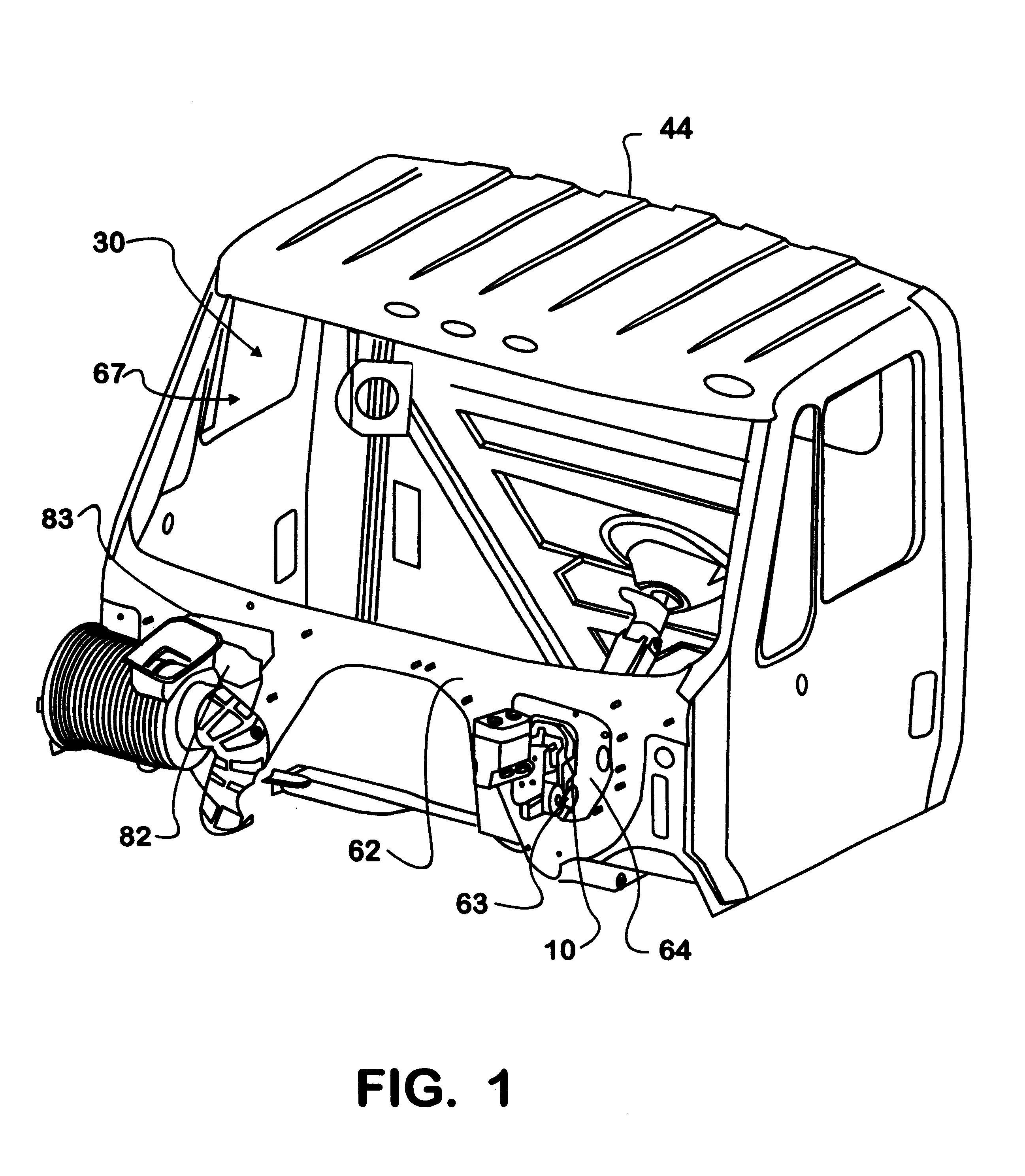
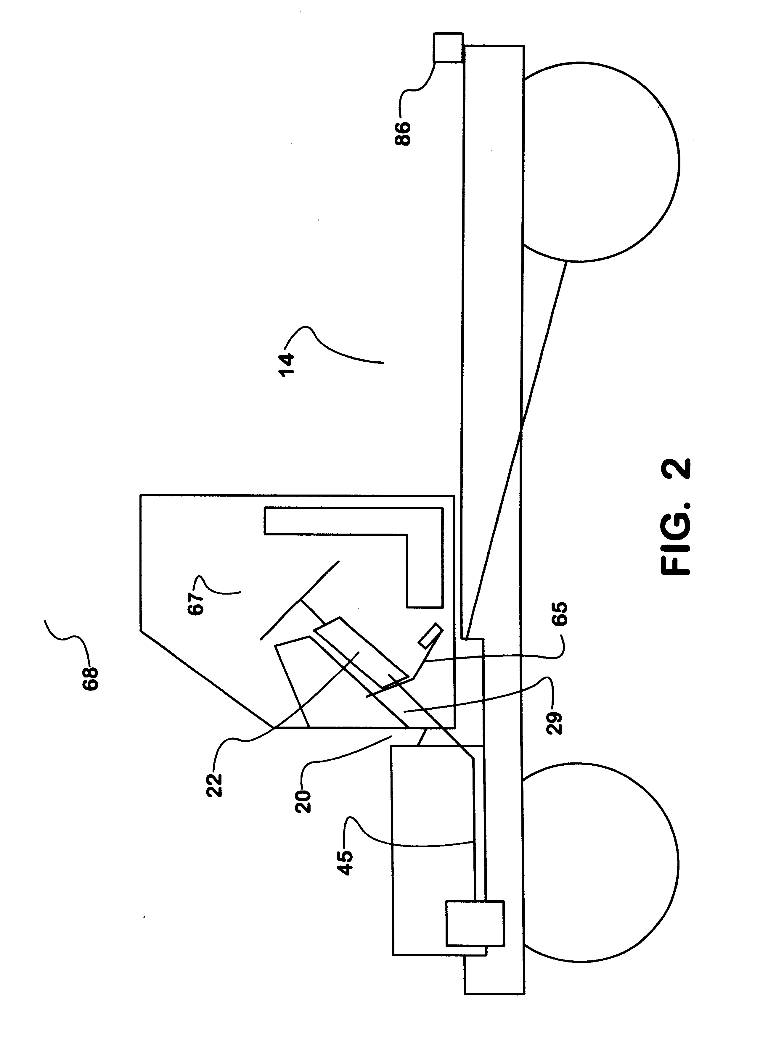
There is shown in FIGS. 1-14 a driver control module 10, a vehicle 14, and various components of each according to the present invention. The driver control module 10 of the present invention allows assembly of the brake pedal 11 and one or more steering column components 12 to a first dash engagement piece 13 and the subsequent installation of the resulting assembled driver control module 10 in the vehicle 14 as a unit. The first dash engagement piece 13 is designed to be the foundation of the driver control module 10 and to be mounted to the dash panel 62 of the cab 44. The dash panel 62 defines a first driver control module opening 63 as can be best seen in FIG. 1. The first driver control module opening 63 of the dash panel 62 is of a shape such that the first dash engagement piece 13 spans the first driver control module opening 63 when the driver control module 10 is installed in the vehicle 14. The dash panel 62 and first the dash engagement piece 13 both contain engagement m...


PUM


Abstract

A driver control module for a vehicle and a method of assembling and installing the driver control module in the vehicle. The driver control module includes the operator control pedals, the steering column and a large portion of the brake actuation system of the vehicle. The driver control module is designed to be assembled as a unit and then mounted to the dash of the vehicle.

Description

This invention relates to a driver control module for a mobile vehicle such as medium or heavy duty truck, the vehicle with the driver control module installed, and the process of installing the driver control module into a vehicle. The driver control module contains the steering column, brake, clutch, and accelerator pedals, and brake valves. The module may be easily installed in openings on either the right or left sides of a symmetrical dash panel of a vehicle cab depending on whether the vehicle is right hand or left hand drive. A cab air conditioning module is installed on the opposite side opening of the driver control module thereby reducing assembly line efforts. The driver control module may be separately assembled, brought to the main assembly line as a unit and readily installed on the vehicle on the line as a unit.PRIOR ARTIn the prior art, driver control modules did not include the steering column for steering wheel mounting, the driver-operated brake, clutch, and accel...

Claims


Application Information

Patent Timeline
Patent Type & Authority Patents(United States)
IPC IPC(8): B62D65/00B60K23/02B60K23/00B60K26/00B60T7/02B60T17/18B62D65/14B62D25/14B60T7/04B60T7/06B60T17/22G05G1/01
CPCB60K23/02B60K26/00B60T7/02B60T17/22B62D25/14B62D65/14B60T7/06Y10T74/20528
Inventor HONEKAMP, CURTIS J.COUSINS, WILLIAMMACRIS, HAROLD F.BADGLEY, THEODORE L.DOWNES, TREVOR T.FLEMING, WILLIAM R.SEXTON, JEFFREY J.
Owner INT TRUCK INTPROP LLC
Learn More