Energy savings circumferential base for cooking utensils

a technology of circumferential base and cooking utensils, which is applied in the field of process of heating cooking utensils, can solve the problems of wasting substantial amount of heat, upseting or pulling off the stove, and affecting so as to improve the efficiency of the cooking process on the stov

Inactive Publication Date: 2003-07-15
ROYER GEORGE R
View PDF4 Cites 12 Cited by
  • Summary
  • Abstract
  • Description
  • Claims
  • Application Information

AI Technical Summary

Benefits of technology

Still another object of the subject invention is to provide an improved structure that improves safety in the usage of a stove when cooking food;
A further object of the subject invention is to provide an improved device that provides optimal energy conservation and safety features for a cooking utensil on a stove surface;
Another object of the subject invention is to provide a device that will improve the efficiency of the cooking process on stoves;

Problems solved by technology

In the usage of burners that are relatively level or flush with the upper surfaces of the stove, there are several heating efficiently concerns involved, and other problems, as more fully described below.
First, a cooking utensil disposed on top of a stove burner is readily susceptible to being moved or pulled off the burner and either upset or pulled off the stove.
This poses a particularly troublesome problem for young children that are playing in and around a stove, as a heated cooking utensil may be inadvertently moved off the stove top and cause accidental burns.
A second problem encountered is that a substantial amount of heat is wasted in the process of heating a cooking utensil on a stove top burner.
In particular, when a pan or other type of cooking utensil is heated on top of such a burner, only the very bottom of the pan is heated, and in the process, the heating takes a greater period of time since only the bottom is heated and significant amount of heat rises up and around the sides of the cooking utensil and into the air.
This wasted heat represents a loss of energy that could be otherwise used to help heat the cooking utensil in the process and thus save energy.
One of the causes of this heat loss in this regard is that the bottom of the cooking pan, or other such utensil only covers a partial part of the upper surface area of the burner.
As a result that portion of the burner not covered by the bottom of the pan rises upwardly in the air around the pan, a substantial amount of which is thus wasted.

Method used


Image

  • Energy savings circumferential base for cooking utensils
  • Energy savings circumferential base for cooking utensils
  • Energy savings circumferential base for cooking utensils

Examples


Embodiment Construction

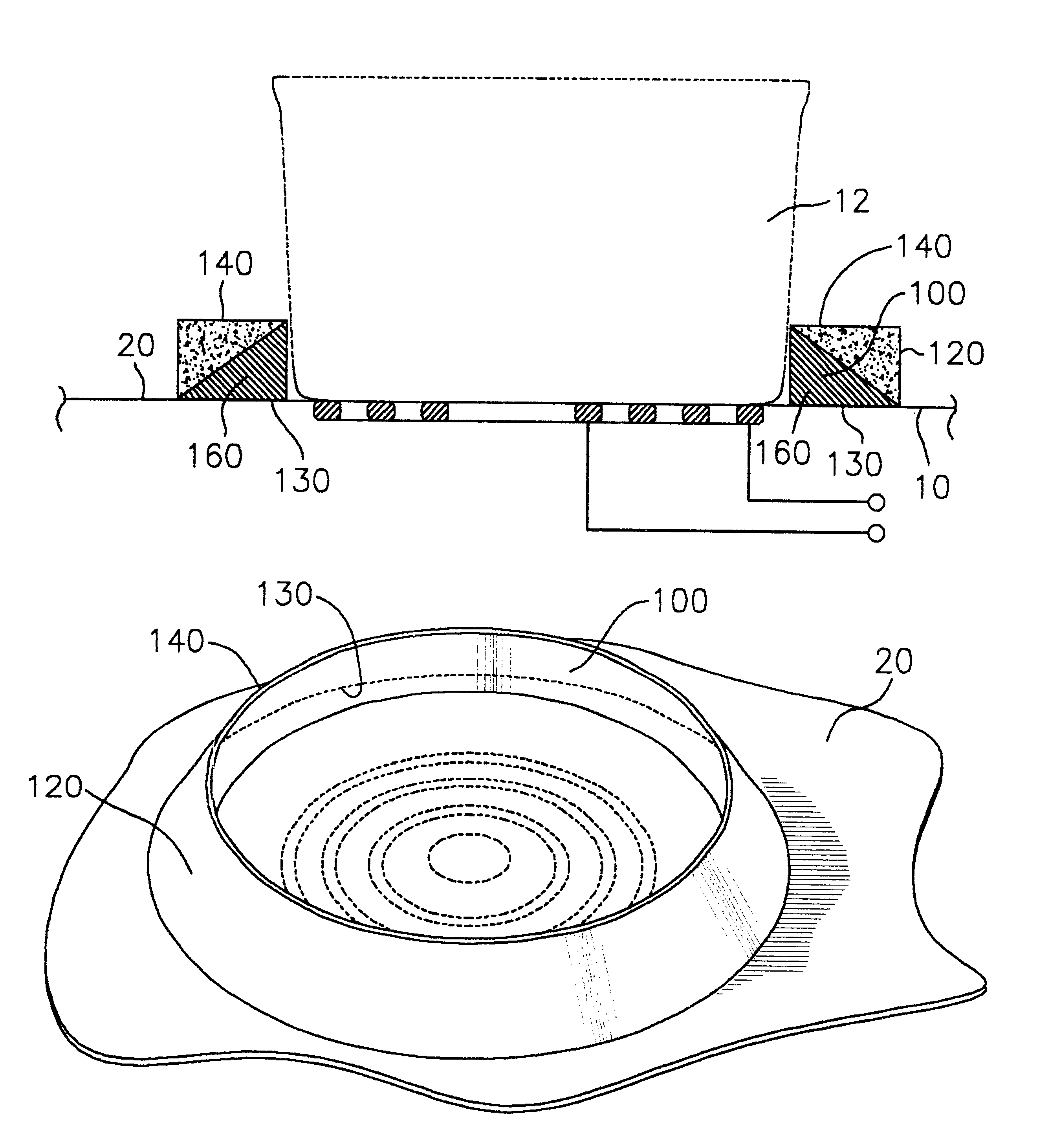
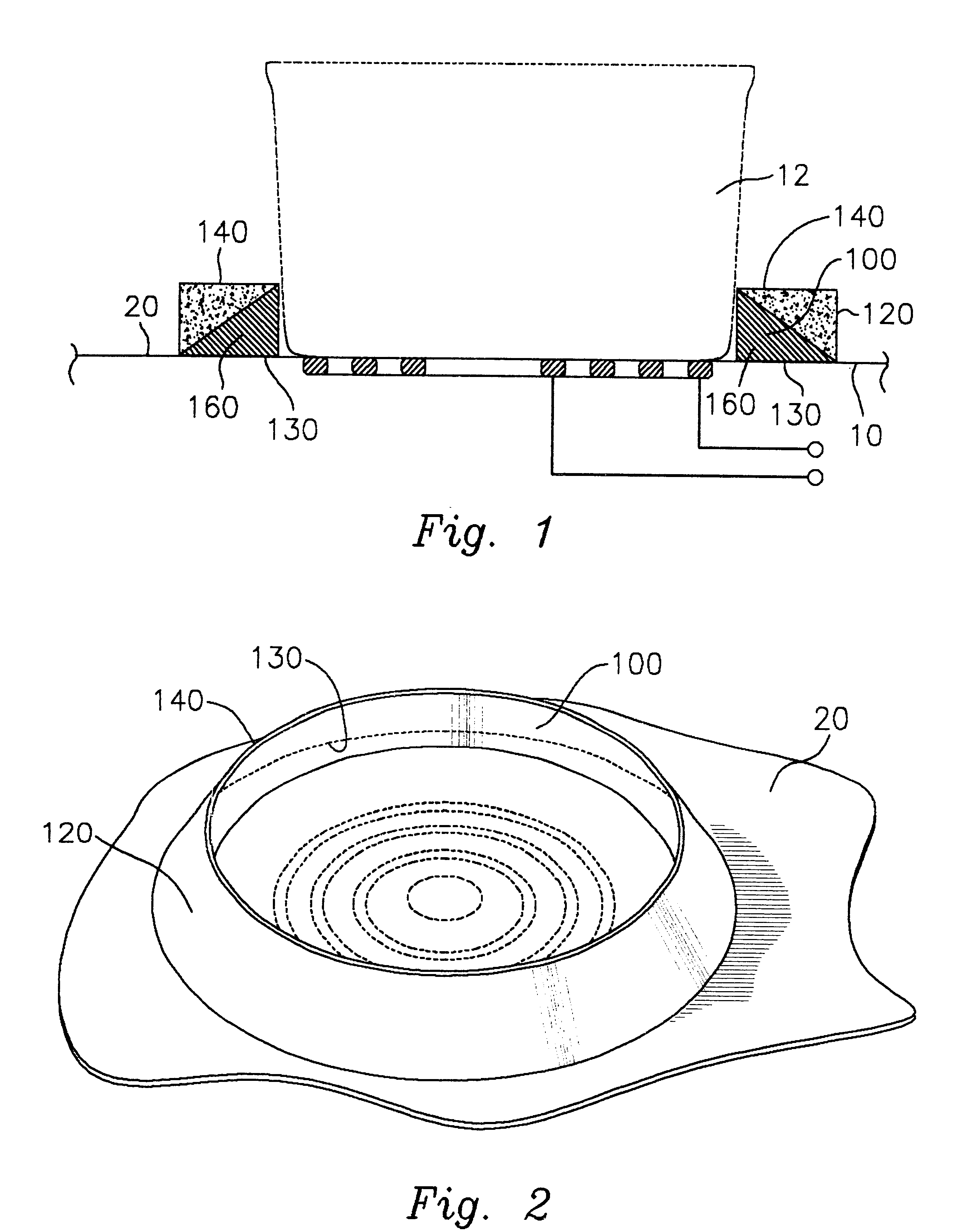
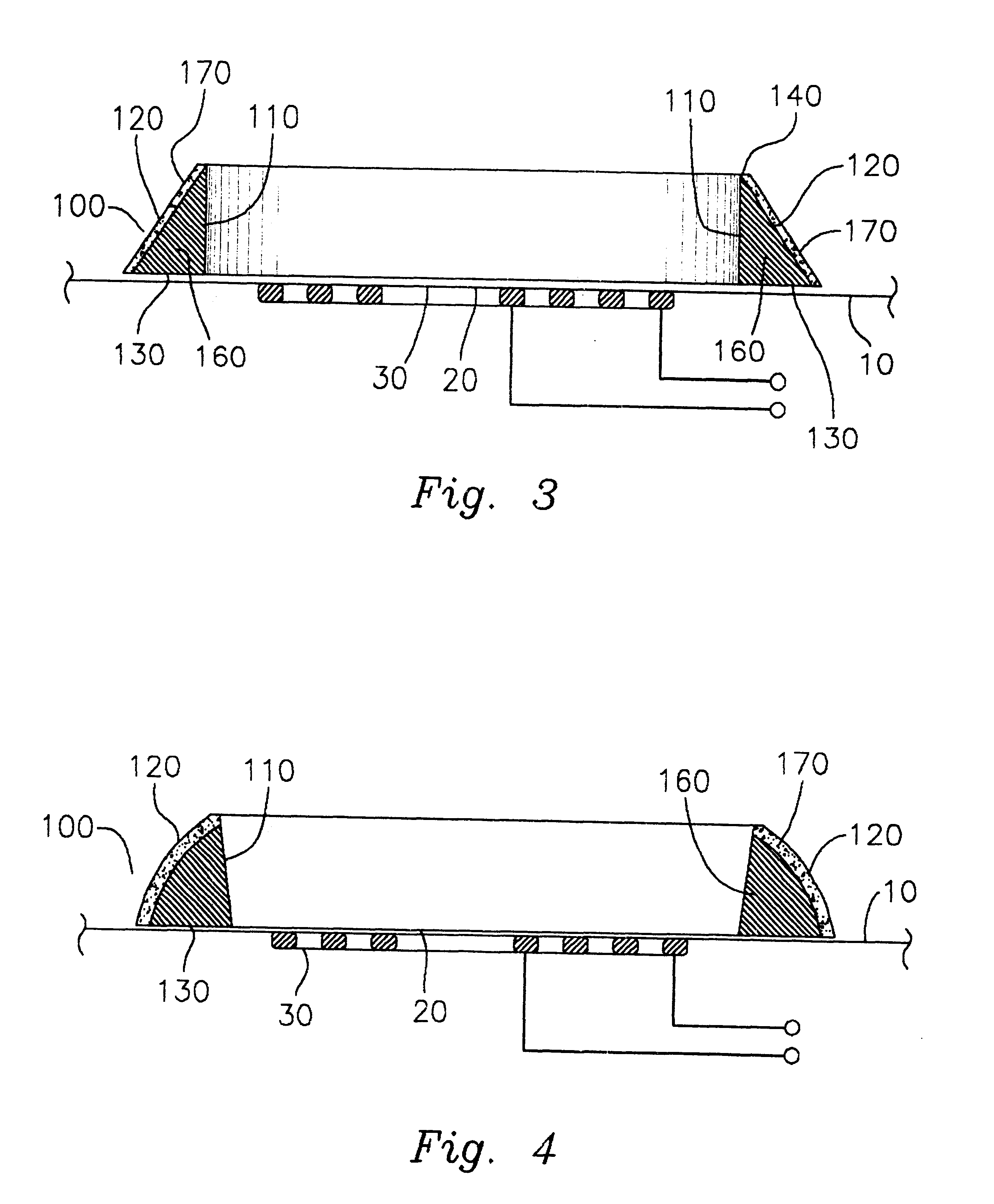
The subject device is an energy savings perimeter member for cooking utensils placed on a stove burner with the subject device being a perimeter member adapted to encircle in part or in whole the bottom circumference of the cooking utensil so that the lower bottom circumference of the cooking utensil is partially or wholly surrounded by the inner circumferential wall of the perimeter member with the perimeter member structured to receive heat from the stove burner on its lower surface. The ring member then transfers such heat upwardly into the inner circumferential surface of the perimeter member to be transferred to the outer surface of the cooking utensil.

In the preferred embodiment as discussed below, the perimeter member may be enclosed, that is a complete surrounding member or may have an incomplete perimeter. Moreover, as discussed the perimeter member is preferably a ring like member adapted to surround comformingly a circular or rounded pan outer surface.

In this latter respe...


PUM


Abstract

The subject device is an energy savings ring for cooking utensils placed on a stove burner with the subject device being a perimeter ring-like member or other generally perimeter member adapted to surround all or part of the outer circumference of the cooking utensil so that part of the outer circumference of the cooking utensil is surrounded by the inner circumferential wall of the perimeter member with the perimeter member being structured to receive heat from the stove burner on its lower surface, and then transfer such heat upwardly into the inner circumferential surface of the perimeter member to be transferred in turn to the outer circumferential surface of the cooking utensil.

Description

DISCUSSION OF PRIOR ART AND BACKGROUND OF INVENTIONThe subject invention pertains mainly to the process of heating cooking utensils on ceramic or flat burner units, although the subject invention may be applicable to other types of stove burners. In this respect, the subject invention comprises an improvement in the efficiency of cooking on stoves.In conventional stove structures, particularly ceramic covered burners, the burner units are usually flush with the upper surface of the stove, or in other burner types may be raised slightly above the upper surface of the stove. In the usage of burners that are relatively level or flush with the upper surfaces of the stove, there are several heating efficiently concerns involved, and other problems, as more fully described below.First, a cooking utensil disposed on top of a stove burner is readily susceptible to being moved or pulled off the burner and either upset or pulled off the stove. This poses a particularly troublesome problem for...

Claims


Application Information

Patent Timeline
Patent Type & Authority Patents(United States)
IPC IPC(8): A47J36/36A47J36/34A47J36/00
CPCA47J36/34A47J36/36F24C15/28
Inventor ROYER, GEORGE R.
Owner ROYER GEORGE R
Why Eureka
Try Eureka