Compact antenna not easily broken by external force, stable in communication performance and excelling in durability

a compact antenna and external force technology, applied in the direction of loop antennas with ferromagnetic cores, non-resonant long antennas, protective materials radiating elements, etc., can solve the problems of easy cracking or chipping, unstable communication performance of the coil, and easy deterioration of the communication performance of the compact antenna

Inactive Publication Date: 2003-08-05
ALPS ALPINE CO LTD
View PDF4 Cites 10 Cited by
  • Summary
  • Abstract
  • Description
  • Claims
  • Application Information

AI Technical Summary

Benefits of technology

This configuration of linking external faces of the plurality of unit cores by linking members and arranging the linking members to be bendable between the unit cores serves to protect the unit cores from destruction and ensures stable communication performance for a long period because any external force would bend the linking members and prevent any major stress from arising in the unit cores. Also, as the unit cores are linked by the linking members, even if any external force deforms the compact antenna, the set spacing between the unit cores will remain unchanged to enable stable communication performance to be maintained. Moreover, as the unit cores are linked by the linking members, the deformation of the coil is regulated by the linked assembly of the unit cores, and deterioration in communication performance due to coil deformation can also be prevented. Furthermore, the arrangement of the linking members on the external faces of the plurality of unit cores enables the compact antenna to be formed in a planar shape, making it possible to provide a thin compact antenna.
The formation of the linking members of elastic bodies eliminates the need to form elastically deformable portions in the linking members, which are indispensable for rigid linking members, and the configuration of the linking members can be simplified with corresponding saving in the manufacturing cost of the compact antenna.
Thus, as the insertion of the plurality of unit cores linked by the linking members into a hollow in the coil makes it possible to insert a plurality of unit cores into a coil in a single process, the time required for inserting unit cores into the coil can be made shorter than inserting a plurality of unit cores one by one into a coil, resulting in corresponding saving in the compact antenna manufacturing cost.
The winding of the coil around the linked assembly of the linking members and the plurality of unit cores linked to them after linking the plurality of unit cores by the linking members as described above can make the integration of the coil with the linked assembly easier than inserting the unit cores and the linking members into the hollow in the wound coil, resulting in corresponding saving in the compact antenna manufacturing cost.

Problems solved by technology

However, since ferrite is a brittle material, a compact antenna made of ferrite, when used in a keyless entry system, is likely to be easily cracked or chipped by the bending stress it is subjected to every time the door handle is operated, with the result that the communication performance of the compact antenna is susceptible to deterioration.
However, in this kind of antenna for use on vehicles, each unit core is held only by the elasticity of the coil and moves independent of the coil, and the set spacing between the unit cores varies with the deformation of the coil, with the consequence that the communication performance of the coil is unstable and, moreover, any major external force is likely to subject the coil to plastic deformation, which means inadequate durability.
Since the plurality of unit coils formed independent of the coil are successively inserted into the hollow in the coil, the insertion of the unit cores into the coil takes a long time, tending to push up the cost of the antenna.

Method used


Image

  • Compact antenna not easily broken by external force, stable in communication performance and excelling in durability
  • Compact antenna not easily broken by external force, stable in communication performance and excelling in durability
  • Compact antenna not easily broken by external force, stable in communication performance and excelling in durability

Examples


example 2

of Compact Antenna

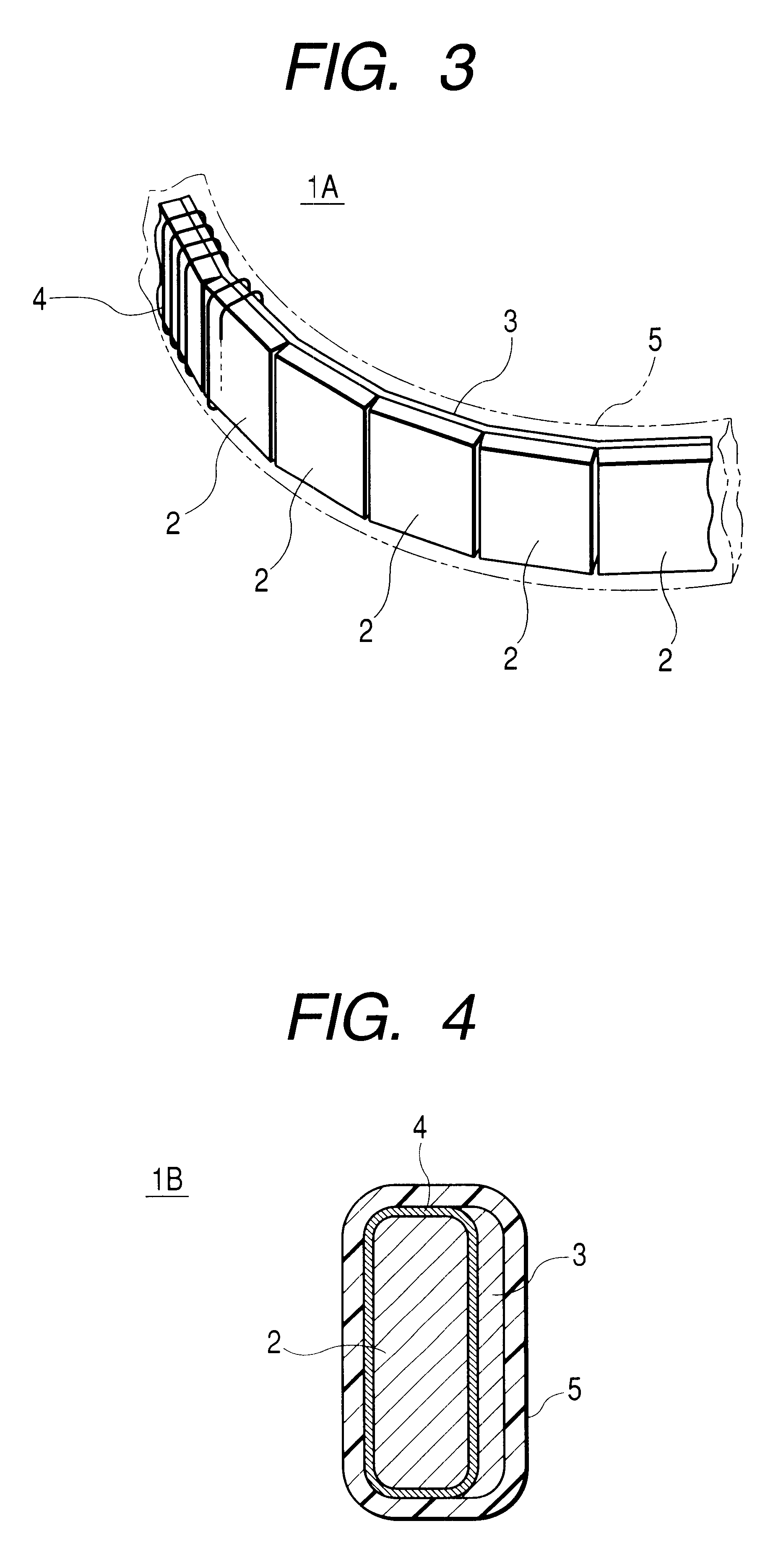
A second example of compact antenna embodying the present invention will be described below with reference to FIG. 4. FIG. 4 shows a section of a compact antenna, which is a second preferred embodiment of the invention.

first embodiment

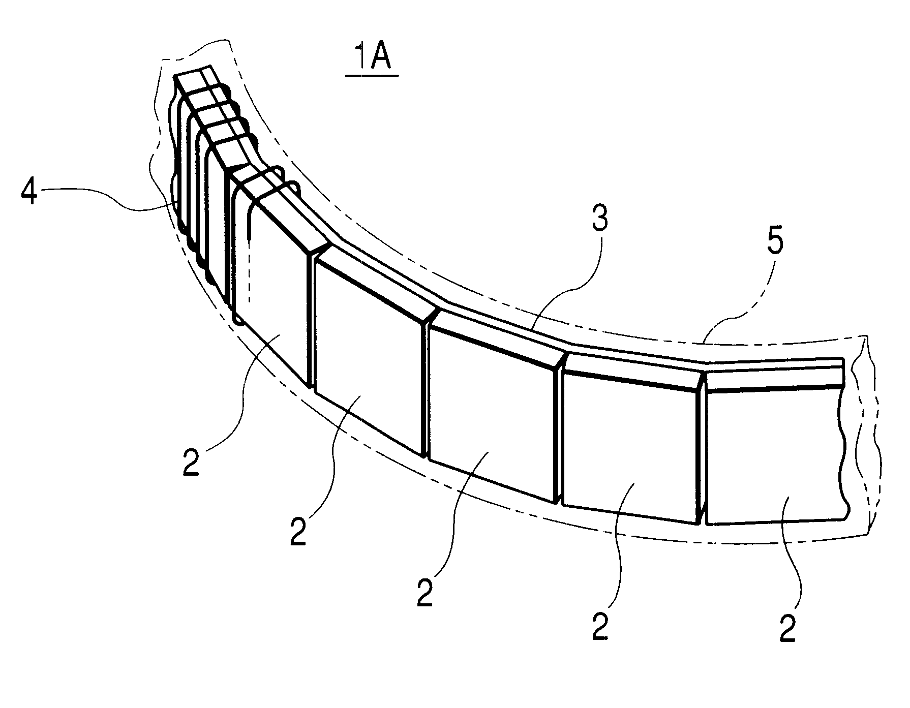
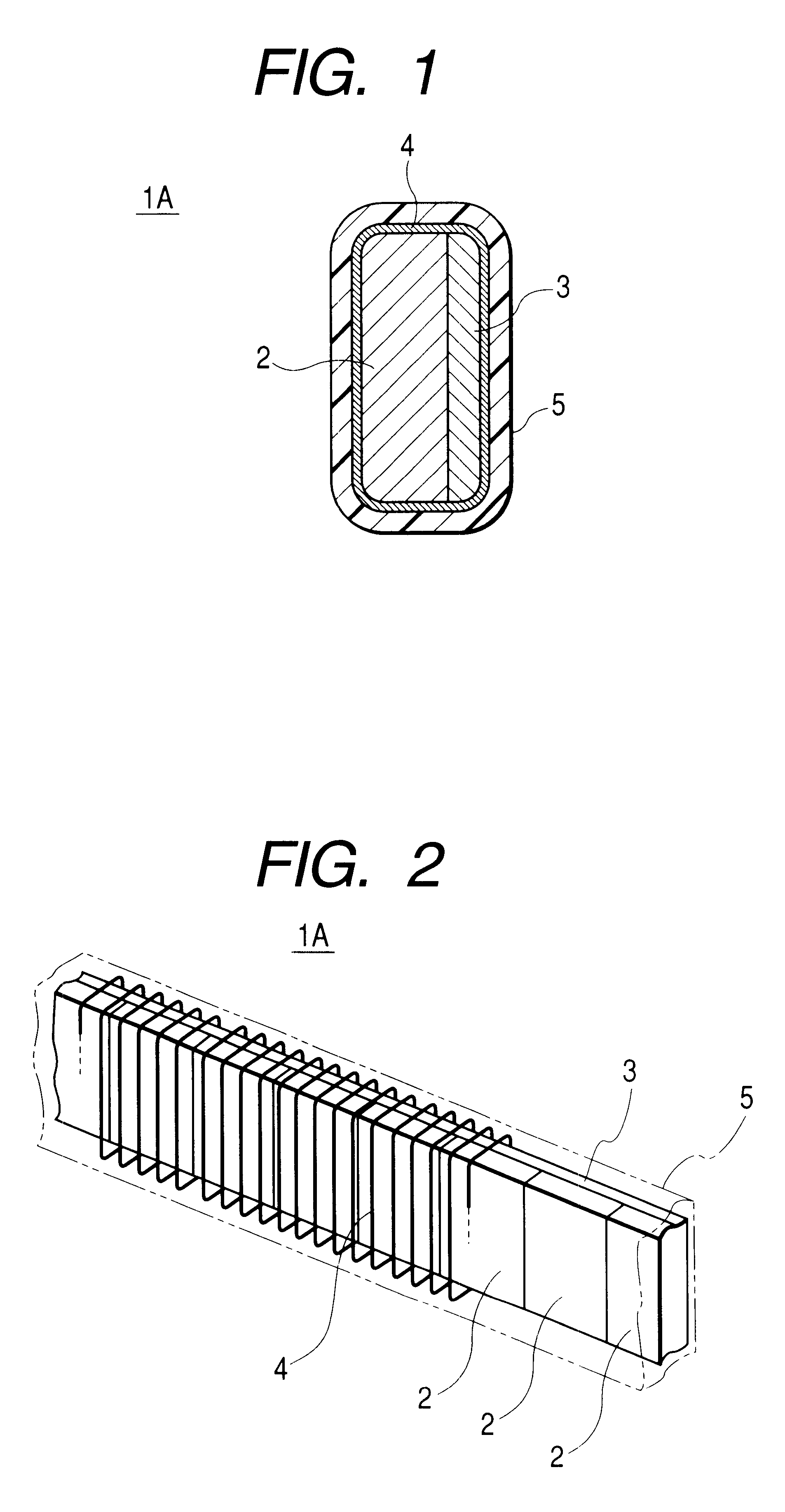
As is evident from FIG. 4, a compact antenna 1B, which is this example, is configured of a coil 4 wound around unit cores 2, linking members 3 fixed to one side of a linked assembly consisting of the unit cores 2 and the coil 4, and a covering 5 for covering around the unit cores 2, the linking members 3 and the coil 4. The description of other aspects of the configuration is dispensed with because they are the same as their counterparts in the compact antenna 1A in the invention.

The compact antenna 1B of this embodiment has similar advantages to those of the compact antenna 1A, which is the first preferred embodiment of the invention.

The compact antenna 1B, which is the second preferred embodiment of the present invention, can be manufactured by a third method comprising a step of winding a coil, a step of inserting a plurality of unit cores into a hollow in the coil, and a step of linking the plurality of unit cores inserted into the hollow in the coil by the linking members.

By th...


PUM


Abstract

A compact antenna is configured of a plurality of planar unit cores, belt-shaped linking members permitting bending or elastic deformation arranged on one side of the plurality of unit cores and linking the unit cores, a coil wound around a linked assembly consisting of the plurality of unit cores and the linking members, and a covering for covering around the linked assembly and the coil. A manufacturing method comprises a step of winding the coil, a step of linking the plurality of unit cores by the linking members, and a step of inserting the plurality of unit cores linked by the linking members into a hollow in the wound coil.

Description

1. Field of the InventionThe present invention relates to a compact antenna for use on vehicles and the like, and a manufacturing method therefor.2. Description of the Related ArtKeyless entry systems are already available for use on vehicles enabling their user to remotely lock or unlock the doors of a vehicle with a signal transmitted from a wireless apparatus carried by the user. In such a keyless entry system, a door handle of the vehicle is provided with a compact antenna electromagnetically coupled to an antenna provided on the wireless apparatus carried by the user to transmit and receive necessary signals. As this compact antenna, one comprising a rod-shaped ferrite core around which a coil is wound is commonly used because of its low cost.However, since ferrite is a brittle material, a compact antenna made of ferrite, when used in a keyless entry system, is likely to be easily cracked or chipped by the bending stress it is subjected to every time the door handle is operated...

Claims


Application Information

Patent Timeline
Patent Type & Authority Patents(United States)
IPC IPC(8): H01Q1/38H01Q1/40H01Q1/36H01Q1/00H01Q7/08H01Q7/00H01P11/00H01Q21/08H01Q7/06H01Q11/08
CPCH01Q1/36H01Q1/38H01Q1/40H01Q7/08
Inventor TESHIMA, KENTARO
Owner ALPS ALPINE CO LTD
Why Eureka
Try Eureka