
Adjustable angle carpentry apparatus

a carpentry and angle adjustment technology, applied in the field of adjustable angle carpentry equipment, can solve the problems of inability to adjust to specific needed angles, difficulty in reading angle increments, and inability to accurately set guides to specific angles

Inactive Publication Date: 2003-08-12
QUICK ANGLE
View PDF18 Cites 33 Cited by
  • Summary
  • Abstract
  • Description
  • Claims
  • Application Information

AI Technical Summary

Benefits of technology

The present invention provides an adjustable carpenter's square for the quick and reproducible measurement of angles and distances, such as radii. The adjustable carpenter's square includes a center bar. The center bar has a grip end and a wing end. Along the center bar, a ...

Problems solved by technology

Though potentially useful for drawing and drafting, the angle increments are difficult to read, especially if the device is employed for actual, field carpentry work or the like, rather than on a drafting or drawing table.
However, the guide lacks the ability to be set to a specific angle with precision, with out the aid of an additional angular measuring device.
Again, the adjustment to specific needed angles cannot be achieved without an additional angle measuring device to verify or select the desired angle between the two legs.

Method used


Image

  • Adjustable angle carpentry apparatus
  • Adjustable angle carpentry apparatus
  • Adjustable angle carpentry apparatus

Examples


Embodiment Construction

The invention provides an adjustable square that quickly and accurately measures and reproduces angles. The adjustable square is referred to herein as a "carpenter's" square, being that carpenter's often use such a device in their occupations. However, the present invention is considered as a potentially useful tool for a variety of applications or occupations besides carpentry, including: masonry, excavation, landscaping, construction and drafting, to name but a few.

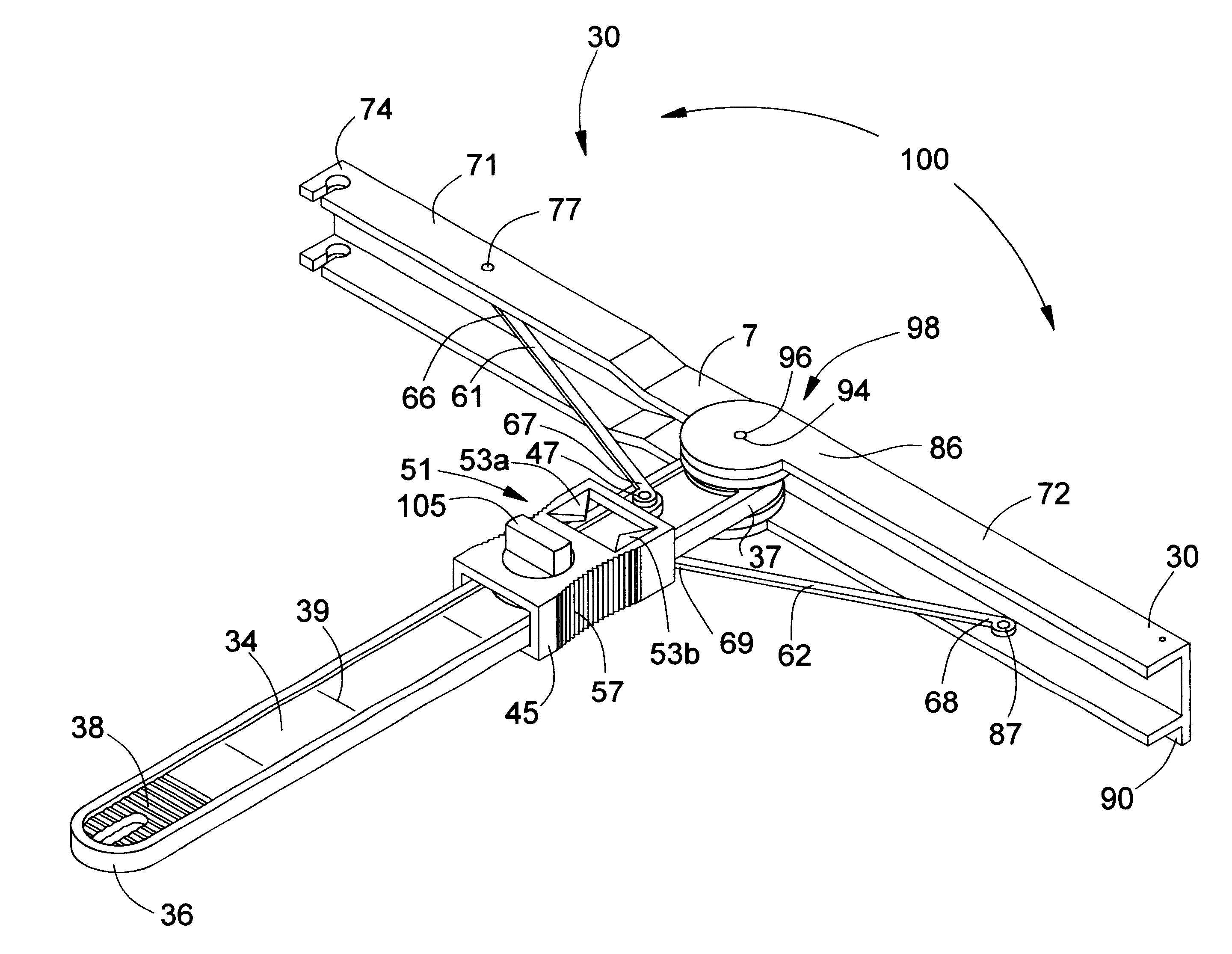
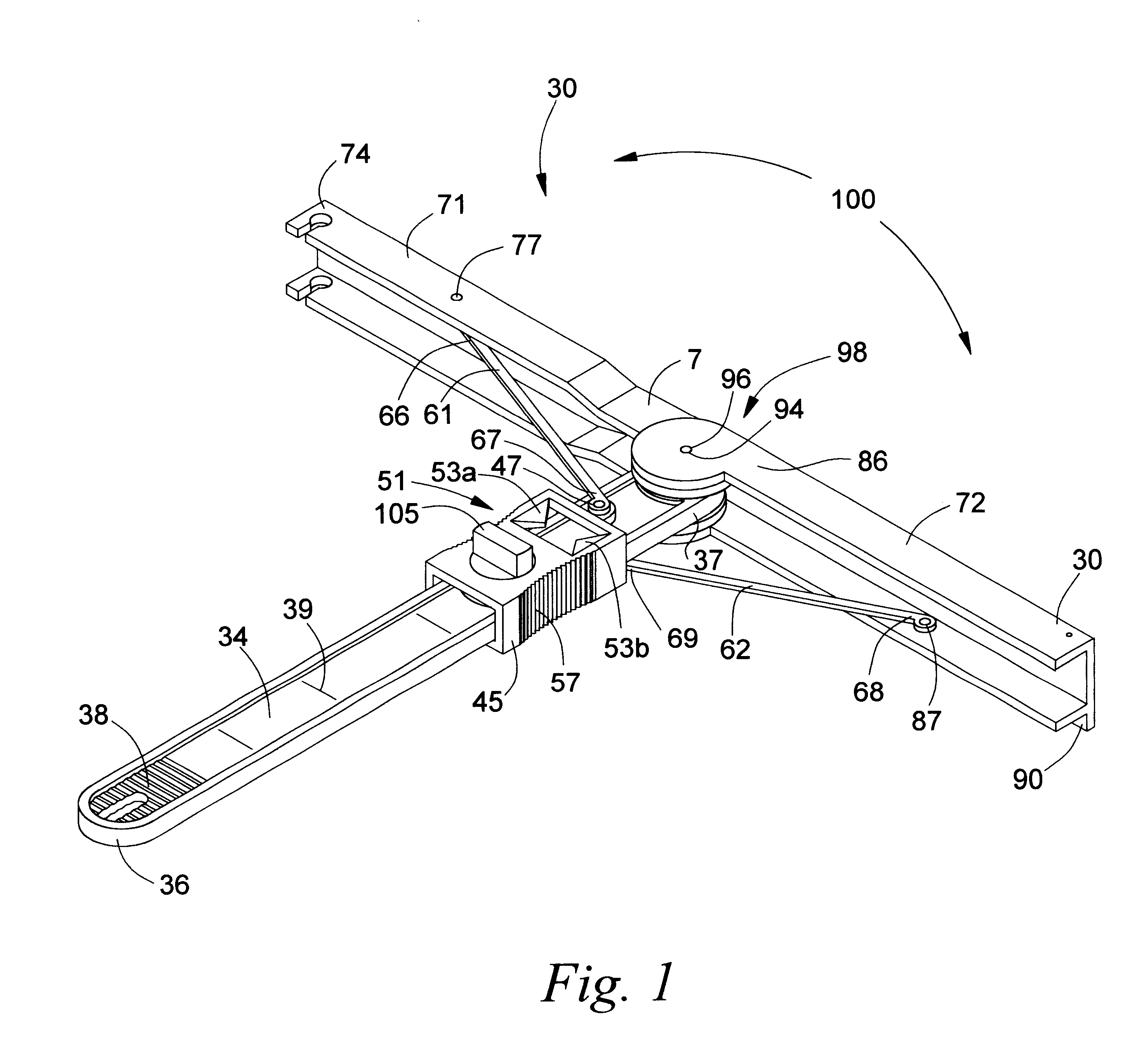
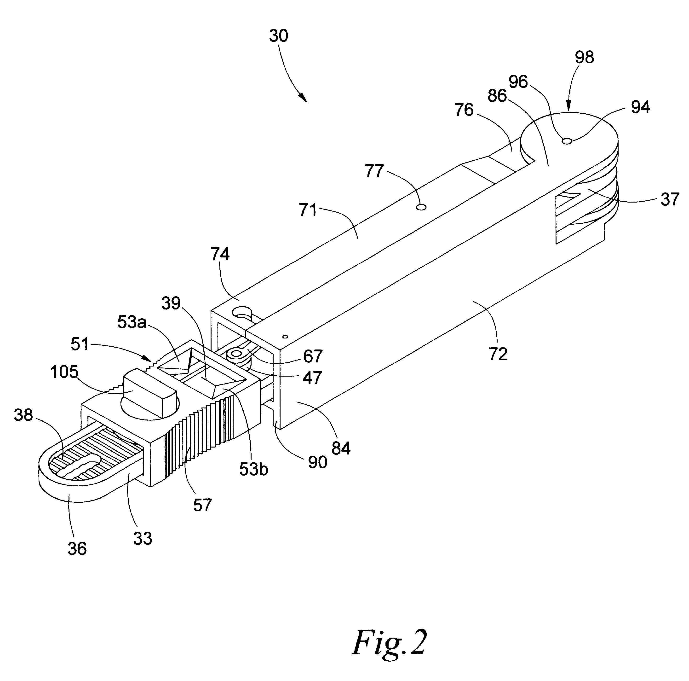
The adjustable square 30 and portions of the adjustable square are shown in FIGS. 1 through 13. As detailed in FIGS. 1 and 2, the adjustable square includes a center bar 33. Being substantially flat in the preferred embodiment, the center bar of the adjustable square includes a top face 34 and a bottom face 35. The center bar also has a grip end 36 opposite a wing end 37. The center bar also preferably includes a thumb grip 38 located proximate to the grip end of the center bar. The thumb grip can be a set of groves, or...


PUM


Abstract

An adjustable carpenter's square for the quick and reproducible measurement of angles and radii. The adjustable carpenter's square includes a center bar that includes a set of indicia. The indicia are any appropriate set of graduations, which may include numerical notations. A indicator slide is receivable onto the center bar. The indicator slide includes a first and second slide strut pivot. A first and second strut attach to the indicator slide. A first wing attaches to the center bar and the first strut. The first wing also includes a first wing strut pivot. The first wing strut pivot hingably connects the first wing to the first strut. The first wing strut pivot attaches to the first strut. A second wing attaches to the center bar and the second strut. The second wing includes a second wing strut pivot. The second wing strut pivot hingably connects the second wing to the second strut. The first and second wings pivotably connect to the center bar. The indicator slide connects to the first and second struts. A measured relation is formed between the first wing with the second wing. The position of the indicator slide on the center bar is relatable to the measured relation by way of the set of indicia displayed on the center bar. The measured relation can include such values as: angles, pitches, radii, diameters, distances, segments, arcs and chords.

Description

The invention relates to an adjustable apparatus for the quick and accurate measurement of angles and distances, and more particularly to a carpenter's type of adjustable square that provides incrementally reproducible angular and linear measurements.Carpentry squares have long been employed as an aid in construction and in craft. Professional carpenters, builders, wood workers, brick layers and masons are but a few trades that require a carpenters's type of square for checking and measuring work materials. Besides professional trades persons, hobbyists and "do-it-yourselfers" also use squares in a wide variety of applications in often encountered situations, each requiring the reliable and quick checking, measurement or establishment of an angle.The standard and well known carpenter's square is a tool that typically has either a triangular or "L" shape. Conventionally, two metal, wood or plastic elements or "legs" are joined at a right angle (90.degree.) to form the tool. The legs ...

Claims


Application Information

Patent Timeline
IPC IPC(8): B25H7/00G01B3/56
CPCB25H7/00G01B3/56
Inventor FARLEY, KENT
Owner QUICK ANGLE
Learn More