Woodworking Machine with Sensing Device

a sensing device and woodworking machine technology, applied in the direction of metal sawing devices, metal sawing accessories, manufacturing tools, etc., can solve the problems of easy injury to the saw blade, large amount of wood flour, and inability to determine the height of the saw blade immediately

Inactive Publication Date: 2011-06-23
META INT
View PDF1 Cites 20 Cited by
  • Summary
  • Abstract
  • Description
  • Claims
  • Application Information

AI Technical Summary

Benefits of technology

The invention has a sensor that can detect when someone tries to use it without wearing protective gear like gloves or masks. It also has a cover to keep out any debris or powder that might damage its sensitive parts while cutting or sanding things.

Problems solved by technology

The technical problem addressed in this patent is the difficulty of quickly and safely determining the height of a saw blade on a table saw during sawing, as the scale that indicates the height is often hidden by the material being cut or produces too much wood flour, which can be dangerous.

Method used


Image

  • Woodworking Machine with Sensing Device
  • Woodworking Machine with Sensing Device
  • Woodworking Machine with Sensing Device

Examples


Embodiment Construction

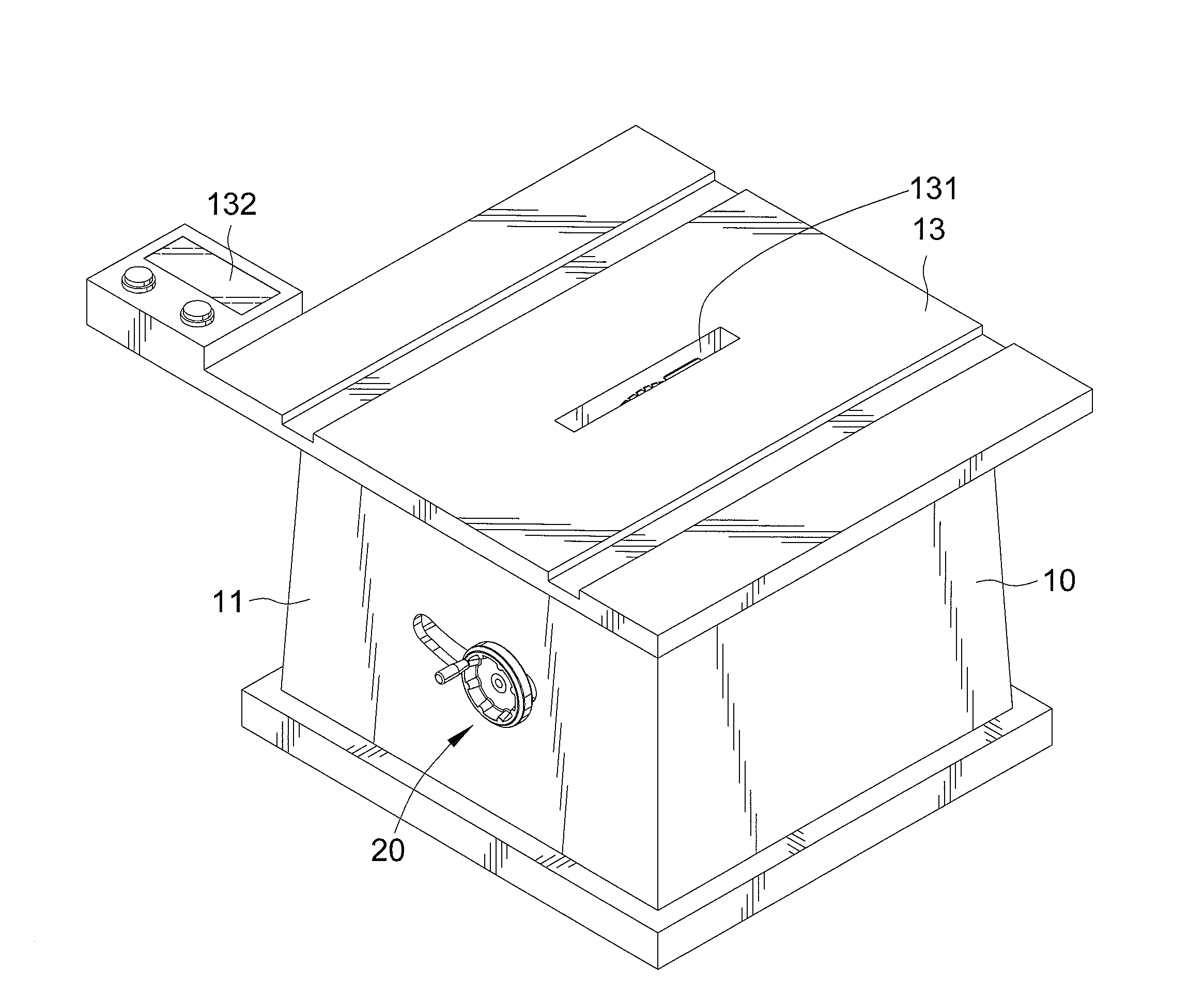
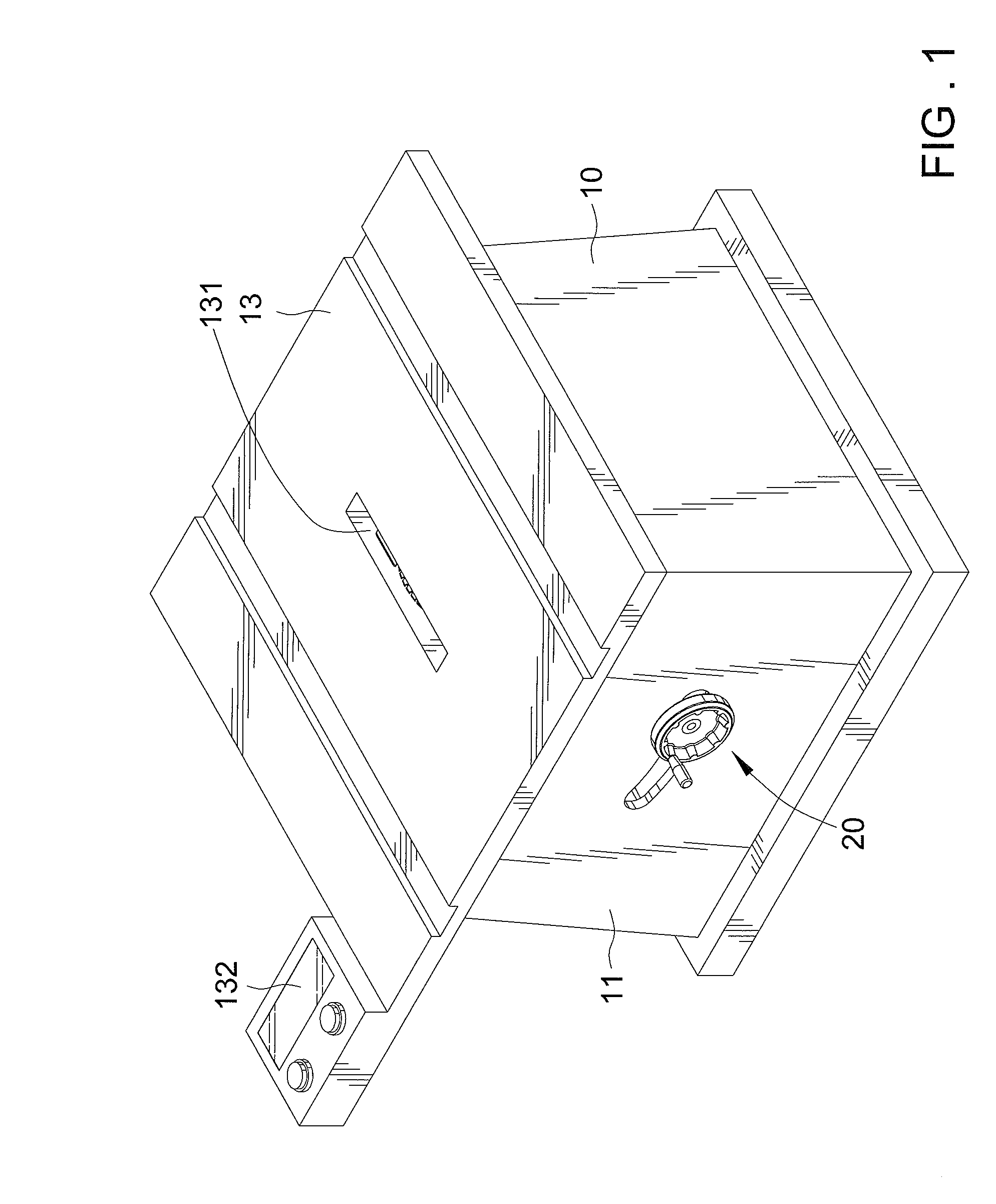
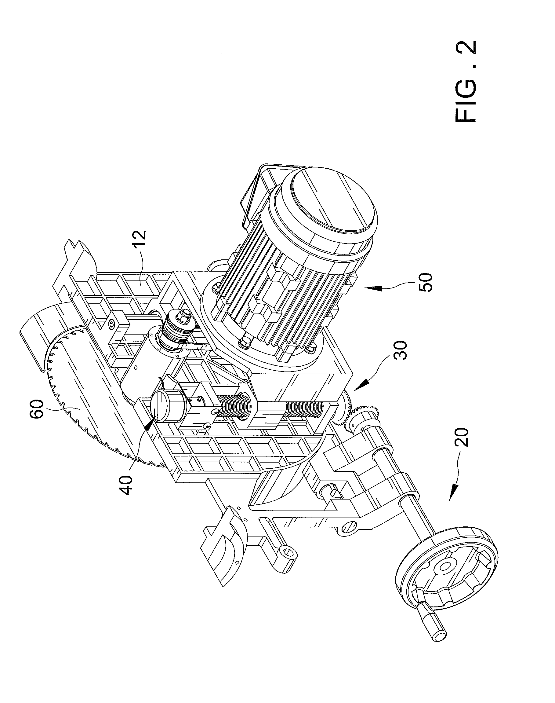
[0020]Referring to FIGS. 1 through 5, they show a woodworking machine which includes a base 10, an active adjustment unit 20, a driven adjustment unit 30, a sensing device 40, an actuating device 50 and a saw 60.

[0021]The base 10 includes a lateral wall 11, a coupled wall 12 and a working surface 13, where a thing desired to be cut is placed on, provided on the top surface of the lateral wall 11 and having a slot 131 inserted by the saw 60 and an indicator 132 showing sensor data which is determined by the sensing device 40. The active adjustment unit 20 is inserted through the lateral and coupled walls 11 and 12. The driven adjustment unit 30 is inserted though the coupled wall 12 and engaged with the active adjustment unit 20. The sensing device 40 is able to sense and measure what's a displacement distance of the driven adjustment unit 30 by adjusting, and further convert the measured displacement distance to a signal to transfer to the indicator 132. The driven adjustment unit 3...


PUM

PropertyMeasurementUnit
Distanceaaaaaaaaaa

Abstract

A woodworking machine comprises a base including a lateral wall, a coupled wall having an end coupled to the lateral wall and a working surface provided on a top surface of the lateral wall and having a slot and an indicator, with a thing desired to be cut being placed on the working surface; an active adjustment unit inserted through the lateral and coupled walls; a driven adjustment unit inserted through the coupled wall and engaged with the active adjustment unit; a sensing device connected to the driven adjustment unit and able to sense an adjusted displacement distance of the driven adjustment unit and further convert the displacement distance to a signal and transfer the signal to the indicator; an actuating device where the driven adjustment unit is mounted on; and a saw connected to the actuating device and exposing from the slot.

Description


Claims


Application Information

Patent Timeline
Owner META INT
Why Eureka
Try Eureka