Feeding mechansim for a woodworking machine

a woodworking machine and mechanized technology, applied in the field of feeding mechanism, can solve problems such as the inclination of the worktable b>1

Inactive Publication Date: 2009-05-28
LIN CHIN CHI
View PDF3 Cites 9 Cited by
  • Summary
  • Abstract
  • Description
  • Claims
  • Application Information

AI Technical Summary

Problems solved by technology

Such tendency may result in inclination of the worktable 1.

Method used


Image

  • Feeding mechansim for a woodworking machine
  • Feeding mechansim for a woodworking machine
  • Feeding mechansim for a woodworking machine

Examples


Embodiment Construction

[0020]Before the present invention is described in greater detail, it should be noted that like elements are denoted by the same reference numerals throughout the disclosure.

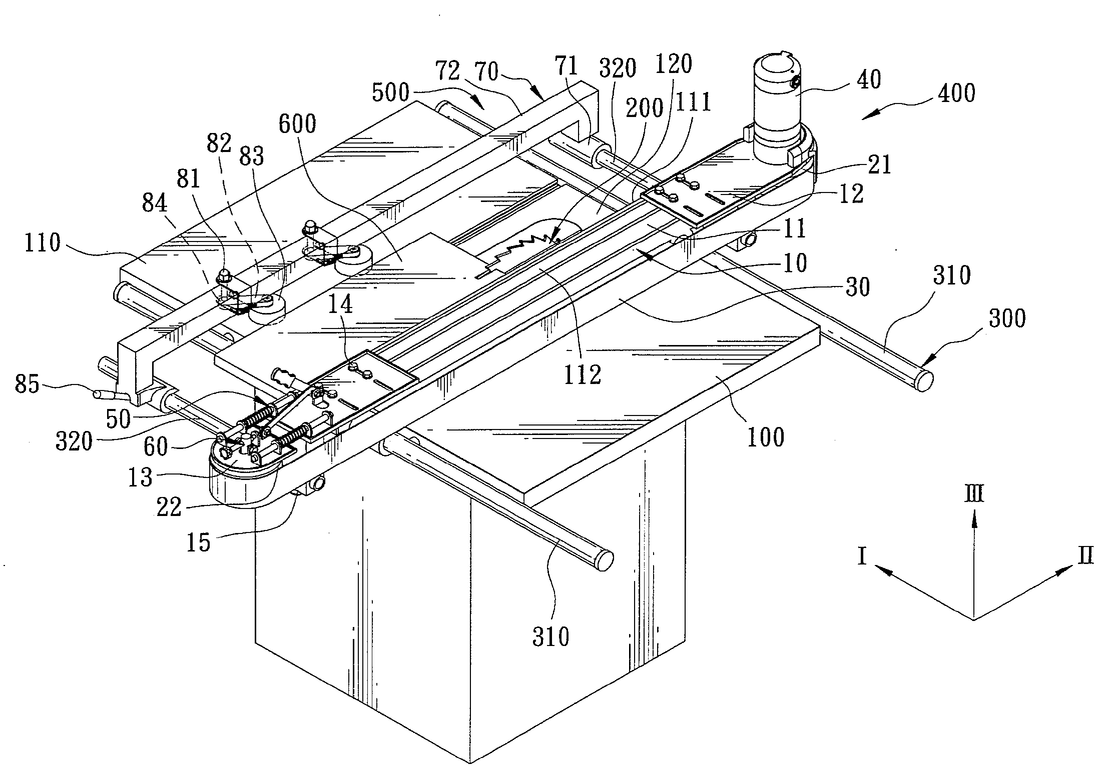
[0021]As shown in FIGS. 3 to 5, the first preferred embodiment of a feeding mechanism according to the present invention is adapted for use with a woodworking machine, such as a table saw machine. The woodworking machine includes a worktable 100 that is disposed for supporting a workpiece 600 thereon and that has a workpiece feeding side 110 and a workpiece discharge side 120 opposite to the workpiece feeding side 110, and a cutter 200 that is in a form of a circular saw and that is provided on the worktable 100 between the workpiece feeding side 110 and the workpiece discharge side 120. The feeding mechanism comprises a rail unit 300, a feeding unit 400, and a press roller unit 500.

[0022]The rail unit 300 includes a pair of parallel main rails 310 extending in a first direction (I) and adapted to be disposed re...


PUM

PropertyMeasurementUnit
movementaaaaaaaaaa
distanceaaaaaaaaaa
widthaaaaaaaaaa

Abstract

A feeding mechanism is adapted for use with a woodworking machine. The feeding mechanism includes a rail unit adapted to be disposed on two sides of a worktable, a feeding unit, and a press roller unit. The feeding unit includes a slidable body adapted to extend across the worktable and disposed slidably on the rail unit, two spaced apart rollers disposed on the slidable body, a belt component trained on the rollers, and a driving component for driving the rollers to rotate along with the belt component. The press roller unit is adapted to extend slidably across the worktable and includes a slidable seat disposed slidably on the rail unit, a press roller connected pivotally to the slidable seat, and a resilient component adapted for biasing the press roller to press the workpiece against the feeding unit.

Description

CROSS-REFERENCE TO RELATED APPLICATION[0001]This application claims priority of Taiwanese Application No. 096144547, filed on Nov. 23, 2007.BACKGROUND OF THE INVENTION[0002]1. Field of the Invention[0003]The invention relates to a feeding mechanism, more particularly to a feeding mechanism for a woodworking machine.[0004]2. Description of the Related Art[0005]FIGS. 1 and 2 illustrate a woodworking machine that comprises a worktable 1 for supporting a workpiece 103 thereon and having a workpiece feeding side 101 and a workpiece discharge side 102 opposite to the workpiece feeding side 101, a pair of parallel slide rails 2 disposed respectively on the workpiece feeding side 101 and the workpiece discharge side 102 of the worktable 1, a cutter 3 provided on the worktable 1, a fence 4 extending across the worktable 1 and slidable along the slide rails 2, and a conventional feeder 5 mounted on the worktable 1. The fence 4 has an abutment surface 401 that permits the workpiece 103 to abut...

Claims


Application Information

Patent Timeline
Patent Type & Authority Applications(United States)
IPC IPC(8): B27B5/29B27B31/00B26D7/06
CPCB27B25/08B27B25/04Y10T83/6563
Inventor LIN, CHIN-CHI
Owner LIN CHIN CHI
Why Eureka
Try Eureka