Woodworking Machining Apparatus

a technology for machining equipment and woodworking, which is applied in the direction of wood-turning machines, metal-working machine components, manufacturing tools, etc., can solve the problems of inability to adjust the height of the tailstock, and the inability to precisely machine the workpiece of wood

Inactive Publication Date: 2013-02-28
LIU RONG CHENG
View PDF4 Cites 7 Cited by
  • Summary
  • Abstract
  • Description
  • Claims
  • Application Information

AI Technical Summary

Benefits of technology

[0011]The holding lever has a handle disposed on one end of the holding lever and a fixing ring fixed on the other end of the holding lever to prevent the holding lever from detaching from the holding base. The height adjusting lever has a threaded portion disposed on one end of the height adjusting lever for screwing through the sliding rod, a handle disposed on the other end of the height adjusting lever, and a buckling ring fixed on the height adjusting lever and located between the threaded portion and handle to prevent the height adjusting lever from detaching from the height adjusting base.

Problems solved by technology

Therefore, the wood workpiece is not precisely machined.
In addition, a height of the tailstock is not adjustable.

Method used


Image

  • Woodworking Machining Apparatus
  • Woodworking Machining Apparatus
  • Woodworking Machining Apparatus

Examples


Embodiment Construction

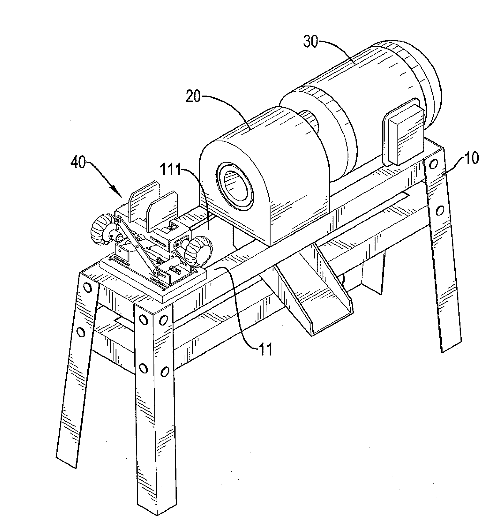
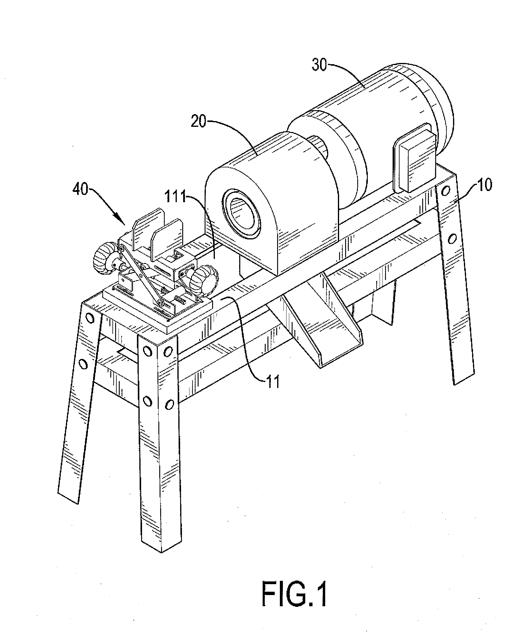
[0019]With reference to FIGS. 1 to 4, a woodworking machining apparatus in accordance with the present invention comprises a bed 10, a machining assembly 20, a driving mechanism 30 and a clamping mechanism 40.

[0020]The bed 10 has a bed-top 11 disposed on a top of the bed 10. The bed-top 11 has a ditch 111 defined through the bed-top 11. The machining assembly 20 is mounted over the ditch 111 in the bed-top 11. The driving mechanism 30 is mounted on the bed 10 for driving the machining assembly 20.

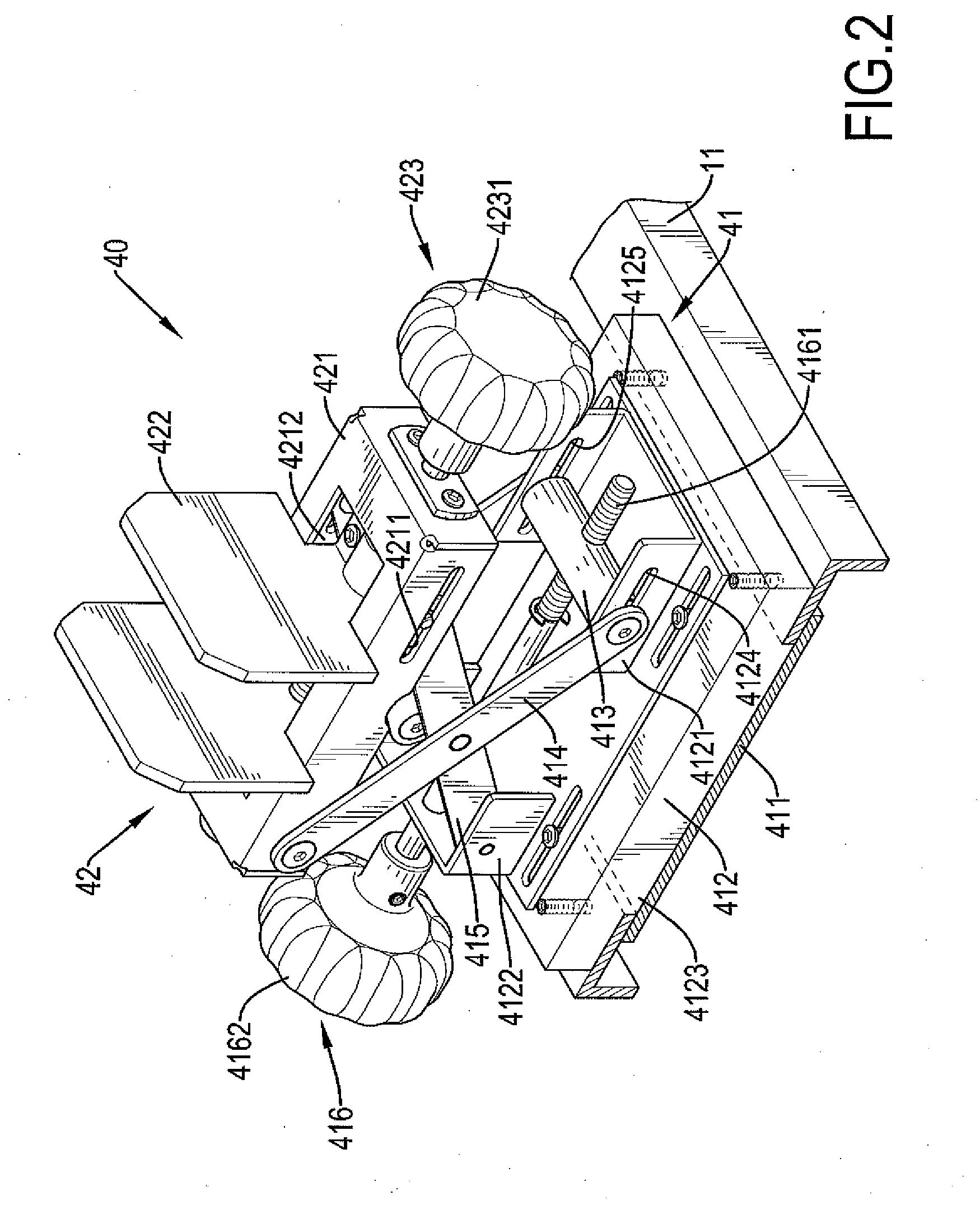
[0021]The clamping mechanism 40 is mounted over the ditch 111 in the bed-top 11. The clamping mechanism 40 is movable along the ditch 111 and relative to the machining assembly 20. The clamping mechanism 40 includes a height adjuster 41 and a holding adjuster 42.

[0022]The height adjuster 41 includes a stabilizing board 411, a height adjusting base 412, a sliding rod 413, a first connecting rod 414, a second connecting rod 415 and a height adjusting lever 416.

[0023]The stabilizing board 411 ...


PUM


Abstract

A woodworking machining apparatus includes a bed, a machining assembly, a driving mechanism and a clamping mechanism. The clamping mechanism is mounted on the bed and is movable relative to the machining assembly. The clamping mechanism has a height adjuster and a holding adjuster. The height adjuster includes a height adjusting base, a sliding rod, first connecting rod, a second connecting rod, a height adjusting lever and a stabilizing board for stably lifting the holding adjuster. The holding adjuster includes a holding base, two clamping sheets and a holding lever for keeping a wood workpiece in a middle of the holding adjuster. The wood workpiece is clamped between the clamping sheets and is lifted by the height adjuster. Therefore, an axis of the wood workpiece can be aligned with the machining assembly.

Description

BACKGROUND OF THE INVENTION[0001]1. Field of the Invention[0002]The present invention relates to a machining apparatus, and more particularly to a woodworking machining apparatus.[0003]2. Description of Related Art[0004]A conventional woodworking machining device includes a workbench, a milling tool, a motor and a tailstock. The workbench has a flat top and a groove defined in the flat top and extending along a length of the workbench. The milling tool and the motor are fixed on the flat top. The motor is connected with the milling tool for driving the milling tool. The tailstock is movably mounted on the flat top of the workbench and is mounted over and is slidable relative to the groove in the workbench. The tailstock includes a base, a first plate, a second plate and a screw bolt. The base is slidable relative workbench along the groove. The first plate and the second plate are respectively mounted on the base. The first plate and the second plate are perpendicular to the base. T...

Claims


Application Information

Patent Timeline
Patent Type & Authority Applications(United States)
IPC IPC(8): B27C7/04
CPCB27C5/06B23Q3/066
Inventor LIU, RONG-CHENG
Owner LIU RONG CHENG
Why Eureka
Try Eureka