Turret for a combat unit

a technology for combat units and turrets, applied in the direction of weapons, weapons, weapons components, etc., can solve the problems of correspondingly large and thus not optimally compa

Inactive Publication Date: 2003-08-19
ALVIS HAGGLUNDS
View PDF9 Cites 8 Cited by
  • Summary
  • Abstract
  • Description
  • Claims
  • Application Information

AI Technical Summary

Problems solved by technology

The conveyor loops (chain belts) of the feed system here require a relatively large space both vertically and horizontally, for which reason the turret, in addition to the area for the crew, is correspondingly larger and thus not optimally compact.

Method used


Image

  • Turret for a combat unit
  • Turret for a combat unit
  • Turret for a combat unit

Examples


Embodiment Construction

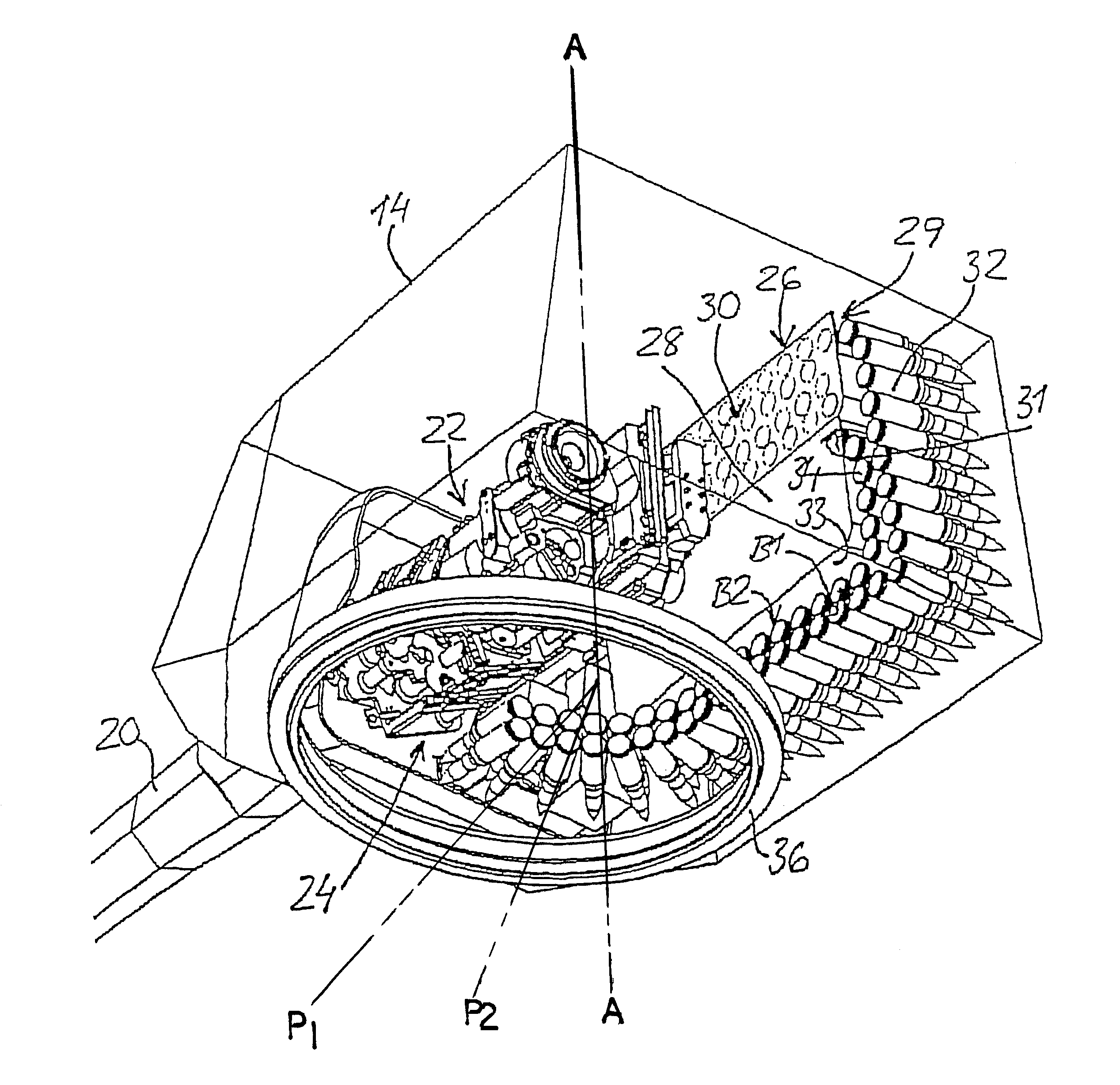
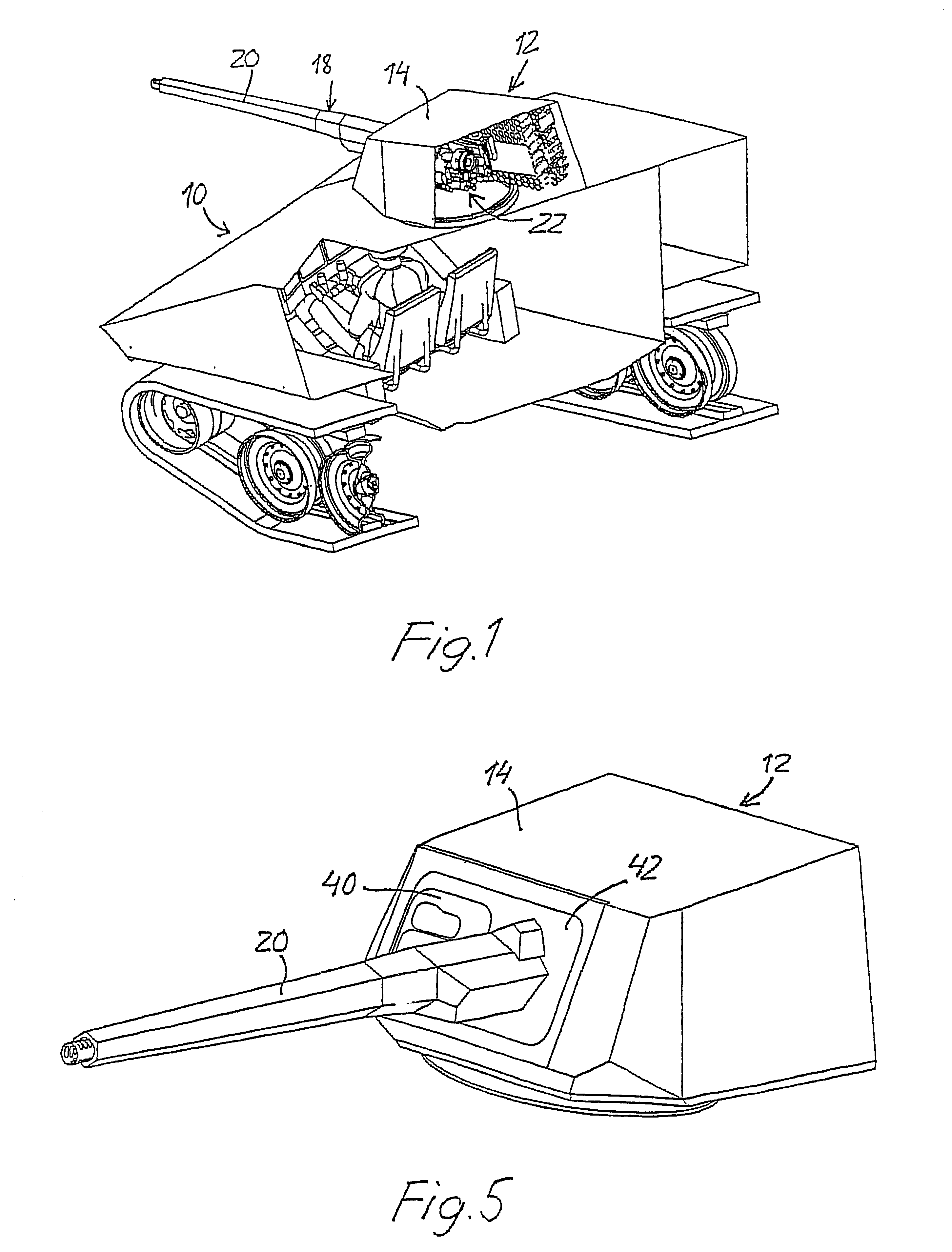
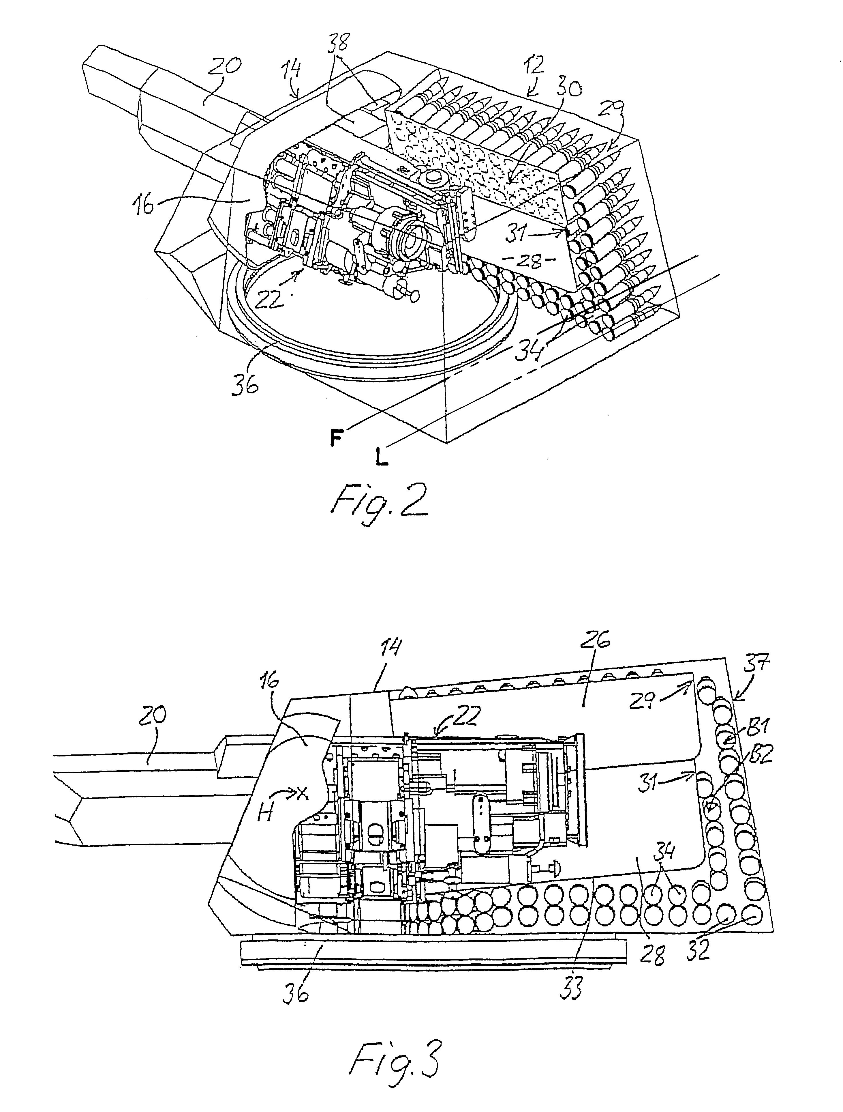
In FIG. 1, reference number 10 generally designates a combat unit, here in the form of a caterpillar-tracked combat vehicle equipped with a compact turret 12 of small dimensions fitted with automatic canon, which turret 12 is mounted on a top face of the vehicle in such a way that it can rotate about a vertical axis. The turret 12 comprises a housing 14 in which there is a weapon holder 16 which supports an automatic canon 18 pivotably about a horizontal axis H (FIG. 3) for elevating the canon. The canon 18 has a barrel 20 projecting from the front face of the housing, and a rear part 22 with an associated loading mechanism 24 on its underside.

Two ammunition magazines 26 and 28, each of which accommodates a loop 30 of ammunition projectiles 32 and 34, respectively, which are carried on chain belts and are preferably of two different types, for example armour-piercing projectiles and high-explosive shells, are placed one on top of the other to one side of the rear part 22 of the cano...


PUM


Abstract

Turret (12) fitted with automatic canon and intended for a combat unit, said turret (12) comprising a turret housing (14) which is intended to be mounted on the outside of the combat unit and can rotate about a substantially vertical axis, and in which turret housing (14) there is a weapon holder (16) for pivotably supporting a canon about a horizontal axis, which canon has a barrel (20) projecting from the turret housing (14) and a rear part (22) with associated loading mechanism (24) situated inside the housing (14). At least one ammunition magazine (26, 28) is arranged to the side of the rear part (22) of the canon and has an outlet (29, 31) for the ammunition belt situated in such a way that the latter can be conveyed from a rear part of the magazine and guided forwards along an underside (33) of the magazine and thereafter curved through ca. 90° about an axis substantially at right angles to the plane of the belt for feeding the projectiles to the loading mechanism (24).

Description

The present invention relates to an unmanned and compact turret for a combat unit, in particular for a combat vehicle, said turret being fitted with automatic canon and comprising a turret housing which is intended to be mounted on an outside of the combat unit and can rotate about a substantially vertical axis, and in which turret housing there is a weapon holder for pivotably supporting a canon about a horizontal axis, which canon has a barrel projecting from the turret housing and a rear part with an associated loading mechanism situated inside the housing, at least one ammunition magazine being arranged in the turret for accommodating a projectile-supporting chain belt which can on the one hand fold between individual chains of the belt about an axis substantially parallel to the projectiles and on the other hand can curve in its own plane about an axis situated outside the belt and substantially at right angles to the plane of the belt.BACKGROUND TO THE INVENTIONIn modern comba...

Claims


Application Information

Patent Timeline
Patent Type & Authority Patents(United States)
IPC IPC(8): F41A9/00F41A9/04
CPCF41A9/04
Inventor FALK, ALFONS
Owner ALVIS HAGGLUNDS
Why Eureka
Try Eureka