System and method for rectifying images of three dimensional objects

a three-dimensional object and image rectification technology, applied in the field of object modeling, can solve the problems of time-consuming searches, difficult realization in practice, and insufficient optimal reduction of the distortion effect of image rectification

Inactive Publication Date: 2003-08-19
MICROSOFT TECH LICENSING LLC
View PDF2 Cites 57 Cited by
  • Summary
  • Abstract
  • Description
  • Claims
  • Application Information

AI Technical Summary

Problems solved by technology

However, such searches are time consuming since the pixels of each image are compared on skewed lines in image space.
However, its realization in practice is difficult because it involves 3D geometric construction.
Although a 2D approach exists, it does not optimally reduce distortion effects of image rectification.
Instead, the distortion minimization criterion is based on a simple geometric heuristic, which may not lead to optimal solutions.
However these image may not be the appropriate size, or in the most desirable coordinate system.

Method used


Image

  • System and method for rectifying images of three dimensional objects
  • System and method for rectifying images of three dimensional objects
  • System and method for rectifying images of three dimensional objects

Examples


Embodiment Construction

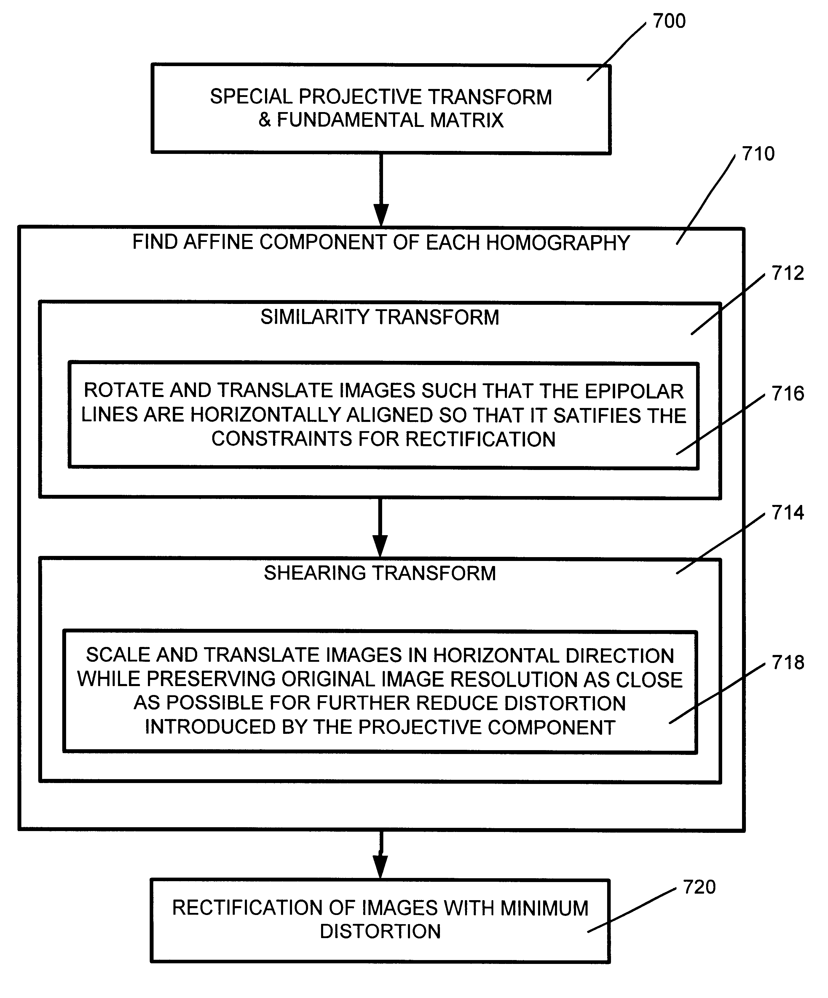
The present invention is embodied in a procedure for computing rectification homographies for a pair of images taken from distinct viewpoints of a 3D scene, as discussed in detail above. FIGS. 8-11 are pictures illustrating one working example of the present invention and show the results of each stage of the working example. The present invention is based on quantifiable 2D image measures and does not require 3D constructions. Further, these measures have intuitive geometric meanings. Namely, as discussed above distortion due to the projective component of rectification is minimized, and additional degrees of freedom are used in the affine component to further reduce distortion to a well defined minimum.

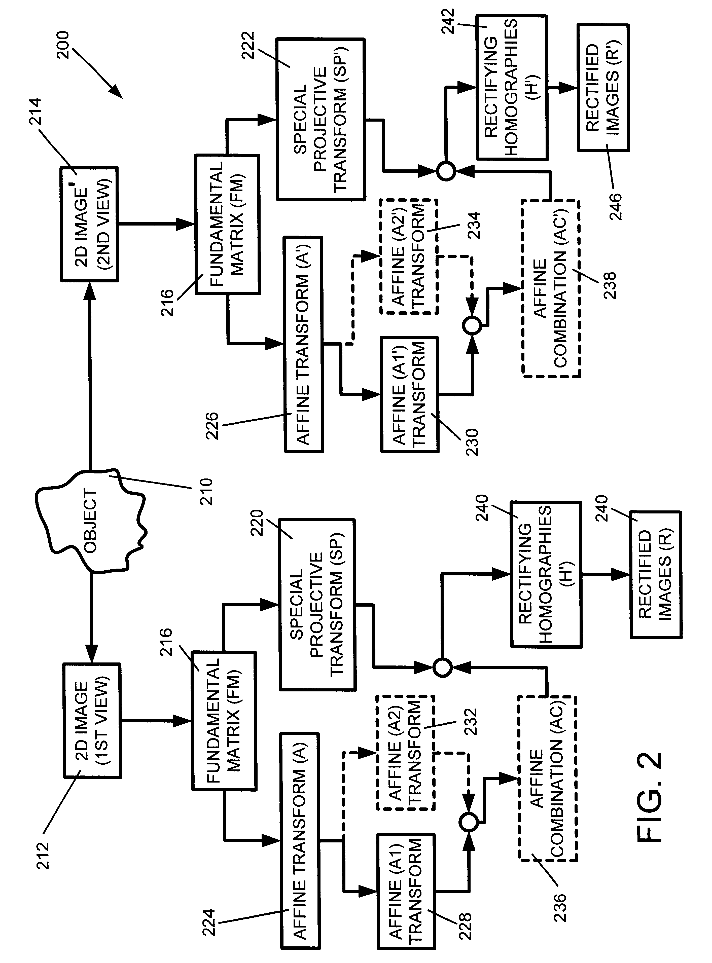
Referring back to FIG. 2 along with FIGS. 8-11, in this working example FIG. 8 shows an original image pair overlaid with several epipolar lines. FIG. 9 shows the image pair transformed by the specialized projective mapping H.sub.p and H'.sub.p 220 and 222. Note that the epipolar li...


PUM


Abstract

The present invention is embodied in a system and method for rectifying two dimensional images of three dimensional (3D) objects for stereo vision processing. In general, the system and method of the present invention computes 2D projective transforms or homographies derived from specialized projective and affine transforms or components. The affine transform is comprised of a first transform and an optional second transform for image rectification. During image rectification of the present invention, optimization techniques are used for reducing the distortion.

Description

1. Field of the InventionThe present invention relates in general to object modeling, and in particular to a system and method for rectifying two dimensional (2D) images of three dimensional (3D) objects.2. Related ArtIn the stereo computer vision field, it is typically assumed that a pair of two dimensional (2D) images of a three dimensional (3D) object or environment are taken from two distinct viewpoints. For certain stereo vision computations, the epipolar geometry of the two images is usually determined first and corresponding points between the two images typically need to satisfy an epipolar constraint. Next, for a given point in one image, a search is initiated for its correspondence in the other image along an epipolar line. In general, epipolar lines are not aligned with coordinate axis and are not parallel.However, such searches are time consuming since the pixels of each image are compared on skewed lines in image space. These types of computations can be simplified and ...

Claims


Application Information

Patent Timeline
Patent Type & Authority Patents(United States)
IPC IPC(8): G06T3/00G06T7/00G06V10/147
CPCG06K9/209G06T3/00G06T7/0075G06T7/593G06V10/147
Inventor ZHANG, ZHENGYOULOOP, CHARLES T.
Owner MICROSOFT TECH LICENSING LLC
Why Eureka
Try Eureka