Transflective liquid crystal display device

a liquid crystal display and transflective technology, applied in static indicating devices, instruments, non-linear optics, etc., can solve the problems of significant light absorption, significant light loss of transflective lcd devices, and significant light loss of backlight devices

Inactive Publication Date: 2003-09-16
LG DISPLAY CO LTD
View PDF6 Cites 94 Cited by
  • Summary
  • Abstract
  • Description
  • Claims
  • Application Information

AI Technical Summary

Problems solved by technology

However, a significant amount of light from the backlight device is lost in the transmissive mode.
As a result, the conventional transflective LCD device suffers a serious decrease in brightness because the closed portion "F" (see FIG. 3) associated with the reflective electrode 49 and with the gate and data lines causes a significant amount of light absorption.

Method used


Image

  • Transflective liquid crystal display device
  • Transflective liquid crystal display device
  • Transflective liquid crystal display device

Examples


second embodiment

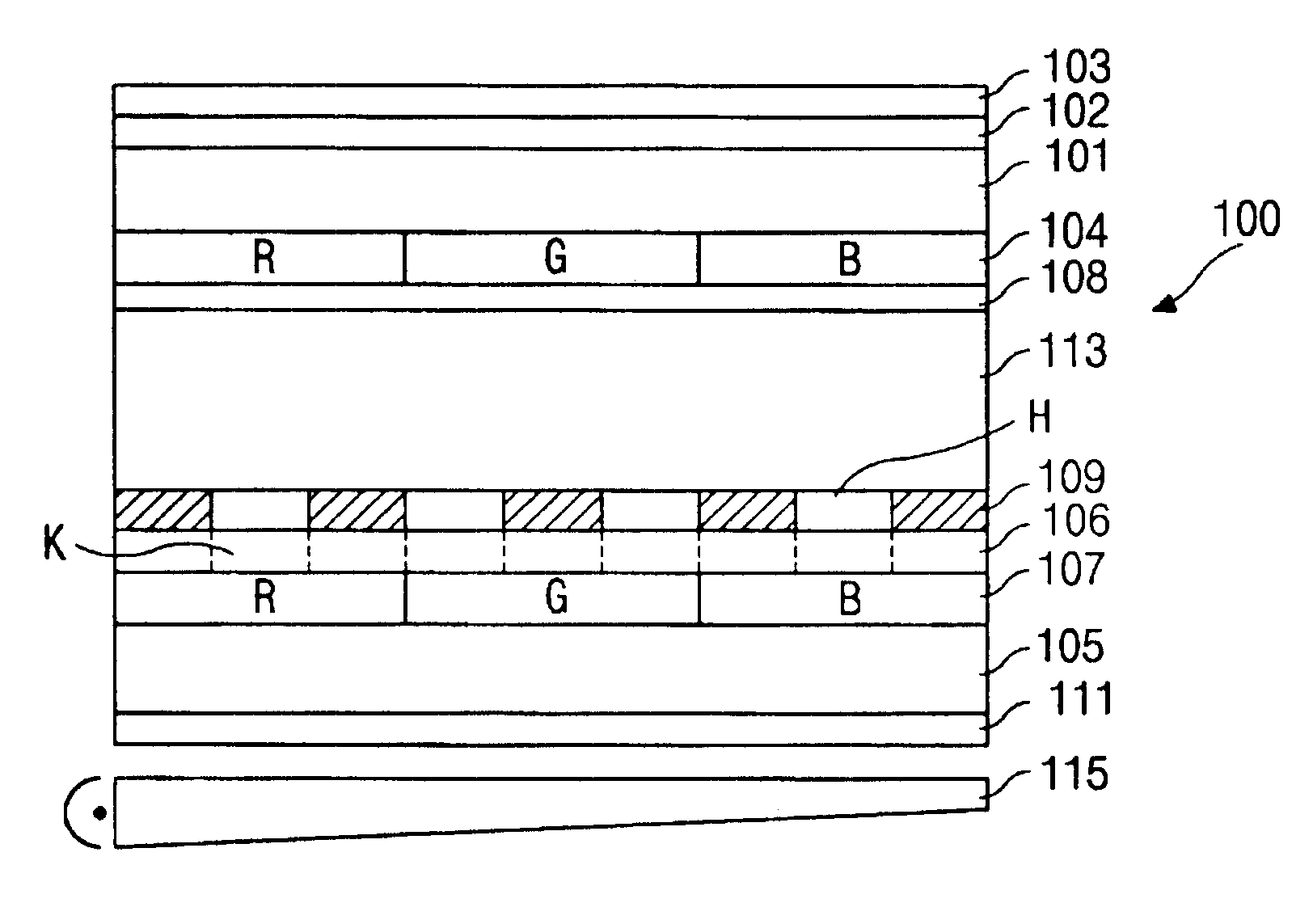
FIG. 9 is a cross-sectional view illustrating a transflective LCD device according to the present invention. As shown in FIG. 9, a lower retardation film 106 has isotropic phase portions "K" comprised of CLC color filters 107. The CLC color filters correspond in size with the transparent portions "H" of the reflective electrode 109. Each CLC color filter 107 transmits a dominant wavelength (color) that can pass through an associated color of the color filter 104. The remainder of the transflective LCD device is generally as depicted in FIG. 5.

FIG. 10 depicts the passage of light from the backlight device 115 through selected components of the transflective LCD device of FIG. 9 when it is operating in a transmissive mode. Only the left-handed circularly polarized light 111a component of the light 115a from the backlight device 115 (see FIG. 5) passes through the CLC polarizer 111. The left-handed circularly polarized light 111a includes red-, green- and blue-light wavelengths. The le...

third embodiment

FIG. 11 is a cross-sectional view illustrating a third embodiment transflective LCD device according to the principles of the present invention. As shown in FIG. 11, a CLC color filter 107 is located in what was the transparent portion "H" of the reflective electrode 109. Again, the CLC color filter 107 transmits the dominant wavelength that can pass through the associated filter of the color filter 104. In this embodiment, the portion "K" of the lower retardation film 106, which corresponds in size to the CLC color filter 107 has an isotropic phase. The remainder of the transflective LCD device is generally as depicted in FIG. 5.

FIG. 12 depicts the passage of light from the backlight device 115 through selected components of the transflective LCD device of FIG. 11 when it is operating in a transmissive mode. Only the left-handed circularly polarized light 111a component of the light 115a from the backlight device 115 passes through the CLC polarizer 111. The left-handed circularly ...


PUM

PropertyMeasurementUnit
wavelength rangeaaaaaaaaaa
wavelengthaaaaaaaaaa

Abstract

A transflective liquid crystal display device that can selectively be used in the transmissive mode or the reflective mode. The transflective liquid crystal panel includes a reflective electrode having a transparent portion, a CLC color filter and a CLC polarizer. Light from a backlight device can pass through the transparent portion of the reflective electrode and into the liquid crystal. Moreover, light from the backlight device that is reflected by the reflective electrode can also pass through the transparent portion and into the liquid crystal without being absorbed by the CLC polarizer. The brightness of the transflective LCD device is thus improved.

Description

This application claims the benefit of Korean Patent Application No. 2000-00398, filed on Jan. 6, 2000, under 35 U.S.C. .sctn.119, the entirety of which is hereby incorporated by reference.1. Field of the InventionThe present invention relates to a liquid crystal display (LCD) device, and more particularly, to a transflective LCD device.2. Description of the Related ArtIn general, a transflective liquid crystal display (LCD) device selectively acts as a transmissive LCD device and as a reflective LCD device. Due to the fact that a transflective LCD device can make use of both internal and external light sources, it can operate in bright ambient light and with low power consumption.FIG. 1 shows a typical thin film transistor liquid crystal display (TFT-LCD) device 11. The TFT-LCD device 11 includes upper and lower substrates 15 and 21 with an interposed liquid crystal 23. The upper and lower substrates 15 and 21 are sometimes respectively referred to as a color filter substrate and a...

Claims


Application Information

Patent Timeline
Patent Type & Authority Patents(United States)
IPC IPC(8): G02F1/13G02F1/1335G02F1/13363
CPCG02F1/133514G02F1/133536G02F1/133555G02F1/13363G02F2001/133565G02F2001/133633G02F2001/133638G02F2413/02G02F2413/09G02F2413/15G02F1/133565G02F1/133631G02F1/133633G02F1/133638G02F1/1335
Inventor MOON, JONG-WEON
Owner LG DISPLAY CO LTD
Why Eureka
Try Eureka