Non-stranded high strength fiber optic cable

a fiber optic cable, non-stranded technology, applied in the direction of optics, fibre mechanical structures, instruments, etc., can solve the problems of high cost, damage to embedded optical fibers, and difficulty in accessing fibers

Inactive Publication Date: 2003-09-16
CORNING OPTICAL COMM LLC
View PDF33 Cites 118 Cited by
  • Summary
  • Abstract
  • Description
  • Claims
  • Application Information

AI Technical Summary

Problems solved by technology

For example, because the electrically conductive strength member surrounds the optical fiber, it is difficult to access the fiber.
Moreover, accessing the central optical fiber may result in damage to the embedded optical fibers.
For example, costs are higher because the helical orientation of the optical fibers necessitates the use of a longer length of optical fiber than the length of the cable in which it resides.
Moreover, from a manufacturing standpoint, it can be more difficult and expensive to strand the strength members and optical fibers.

Method used


Image

  • Non-stranded high strength fiber optic cable
  • Non-stranded high strength fiber optic cable
  • Non-stranded high strength fiber optic cable

Examples


Embodiment Construction

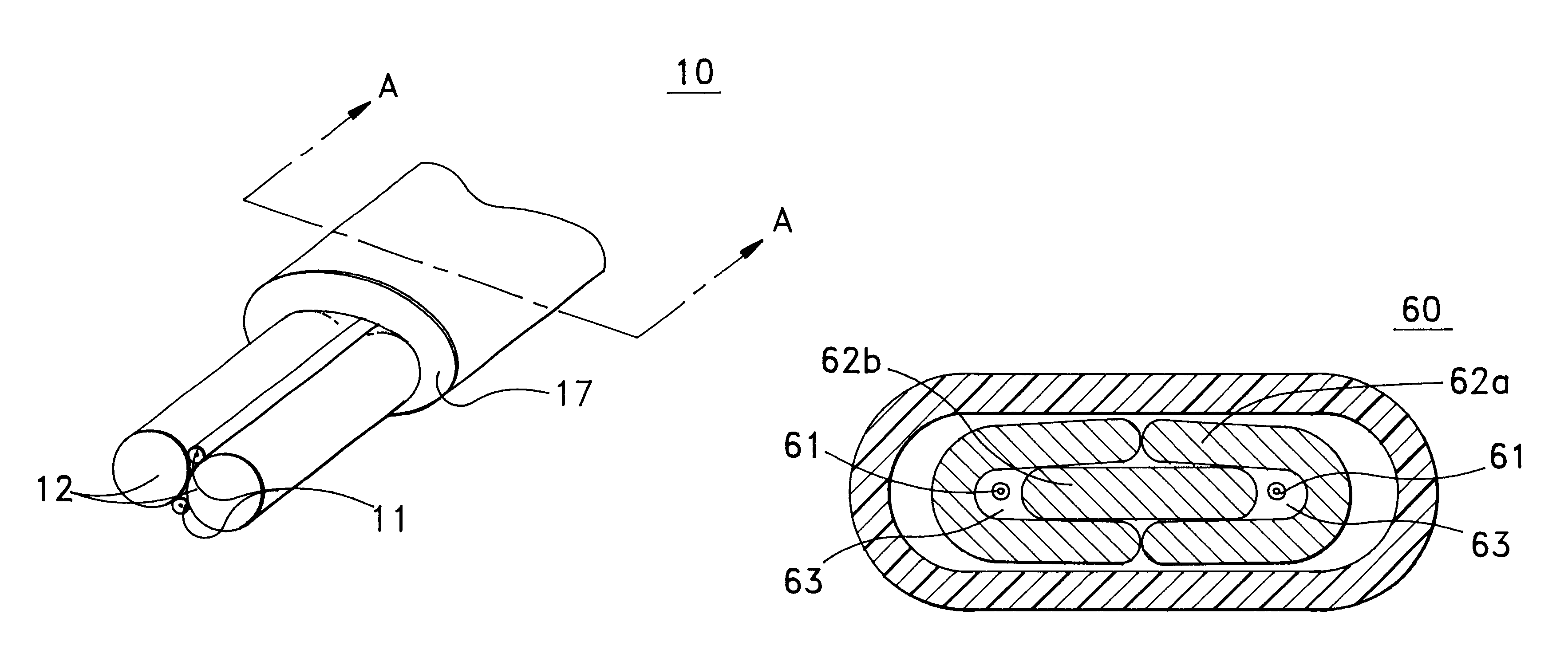
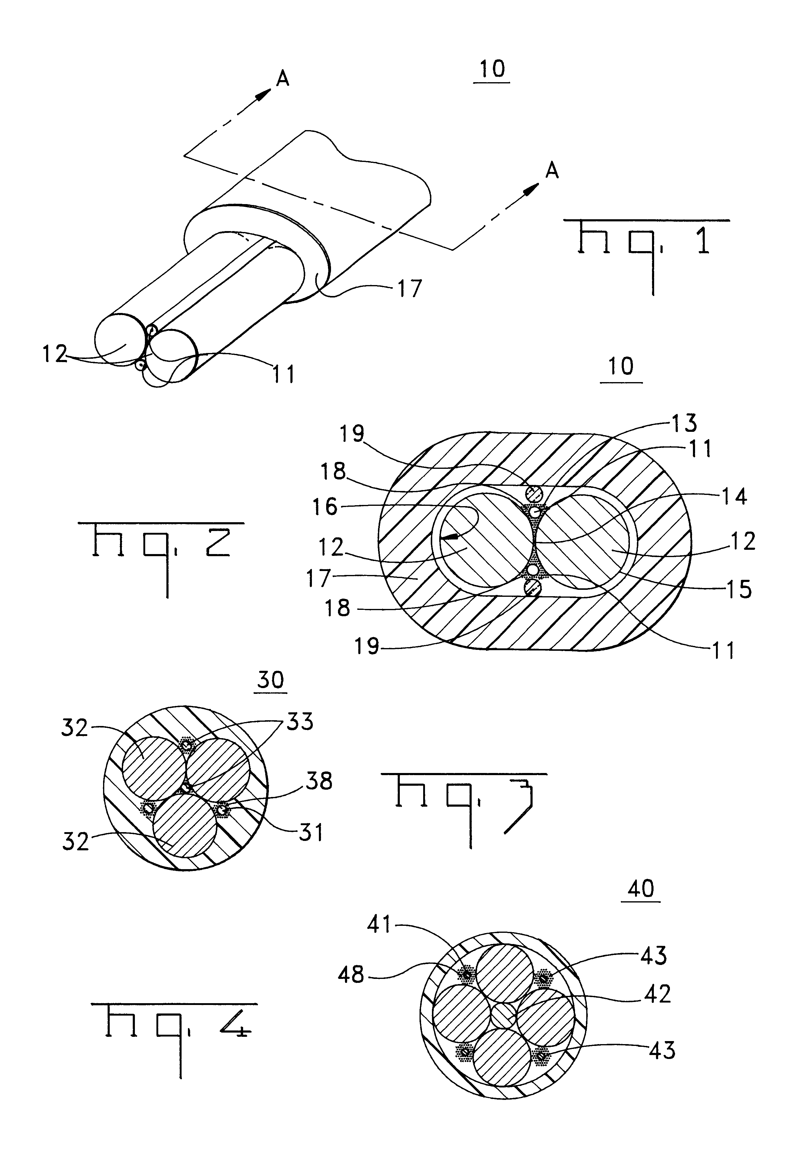
A fiber optic cable 10 according to an embodiment of the present invention is depicted in FIGS. 1 and 2. Fiber optic cable 10 includes at least one interface 14 being formed by a plurality of adjacent support members 12, adjacent interface 14 is at least one retention area 13 that can include an optical fiber component 11 disposed therein. A cable jacket 17 substantially surrounds optical fiber component 11 and support members 12. A cushioning zone 18 can be disposed adjacent to the optical fiber component, and a water-blocking component 19 can be enclosed by the cable jacket 17.

Optical fiber component 11 preferably comprises a single, loose optical fiber. However, component 11 may be loose or tight buffered optical fibers, bundled or ribbonized optical fibers in a common matrix, a stack of optical fiber ribbons in a common matrix or any combination thereof. Each optical fiber preferably includes a silica-based core that is operative to transmit light and is surrounded by a silica-b...


PUM


Abstract

A fiber optic cable having at least one interface being formed by a plurality of adjacent support members. Adjacent the interface is at least one retention area having an optical fiber component disposed therein. The retention area is disposed generally longitudinally and non-helically relative to an axis of the cable. The cable can also include a cable jacket substantially surrounding the support members, a cushioning zone adjacent the optical fiber component, a water-blocking component and / or an interfacial layer at least partially disposed between an outer surface of the support members and the cable jacket.

Description

The present invention relates generally to fiber optic cables.Fiber optic cables include optical fibers that are capable of transmitting voice, video, and data signals. Fiber optic cables have advantages over electrical voice, video and data signal carriers, for example, increased data capacity. As businesses and households demand increased data capacity, fiber optic cables can eventually displace electrical voice, video, and data signal carriers. This demand will require low fiber count optical cables to be routed to end users, for example, businesses and households.Fiber optic cables can typically be used in various applications. For example, fiber optic cables may be suitable for both aerial and buried cable applications. More specifically, a fiber optic cable may be strung between poles and / or buried in the ground before reaching the end user. Aerial and buried cable environments have unique requirements and considerations. Optical fiber cables should meet the unique requirement...

Claims


Application Information

Patent Timeline
Patent Type & Authority Patents(United States)
IPC IPC(8): G02B6/44
CPCG02B6/4429G02B6/44384
Inventor QUINN, CHRIS M.HEDRICK, DOUGLAS S.
Owner CORNING OPTICAL COMM LLC
Why Eureka
Try Eureka