Hydraulically damping rubber bearing

a technology of rubber bearings and damping pads, applied in the direction of resilient suspensions, pivoted suspension arms, machine supports, etc., can solve the problems of rubber bearing destruction

Inactive Publication Date: 2003-09-23
MANNESMANN BOGE
View PDF11 Cites 22 Cited by
  • Summary
  • Abstract
  • Description
  • Claims
  • Application Information

AI Technical Summary

Problems solved by technology

Any deflection angle beyond this leads necessarily to the destruction of the rubber bearing.

Method used


Image

  • Hydraulically damping rubber bearing
  • Hydraulically damping rubber bearing
  • Hydraulically damping rubber bearing

Examples


Embodiment Construction

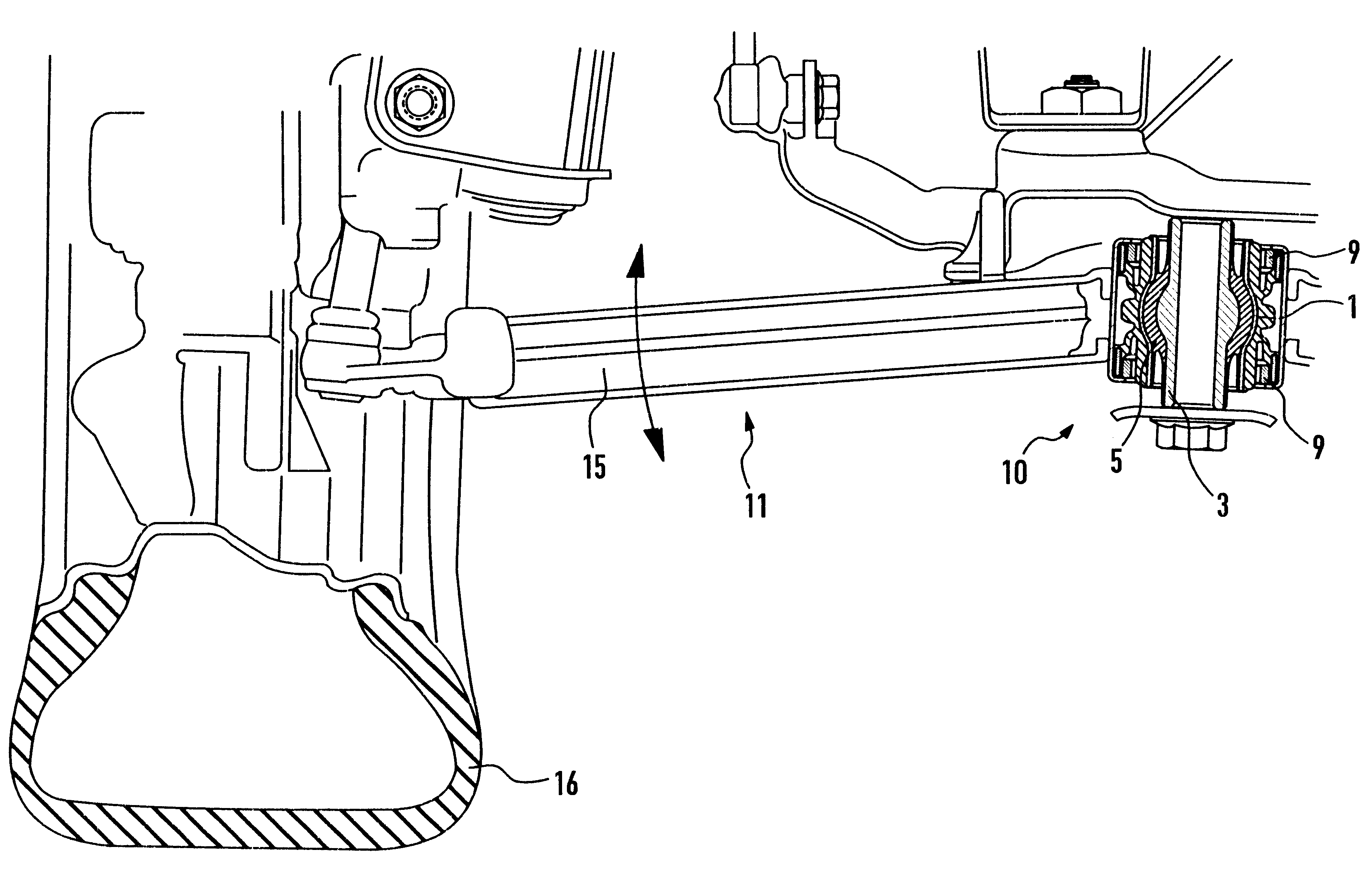
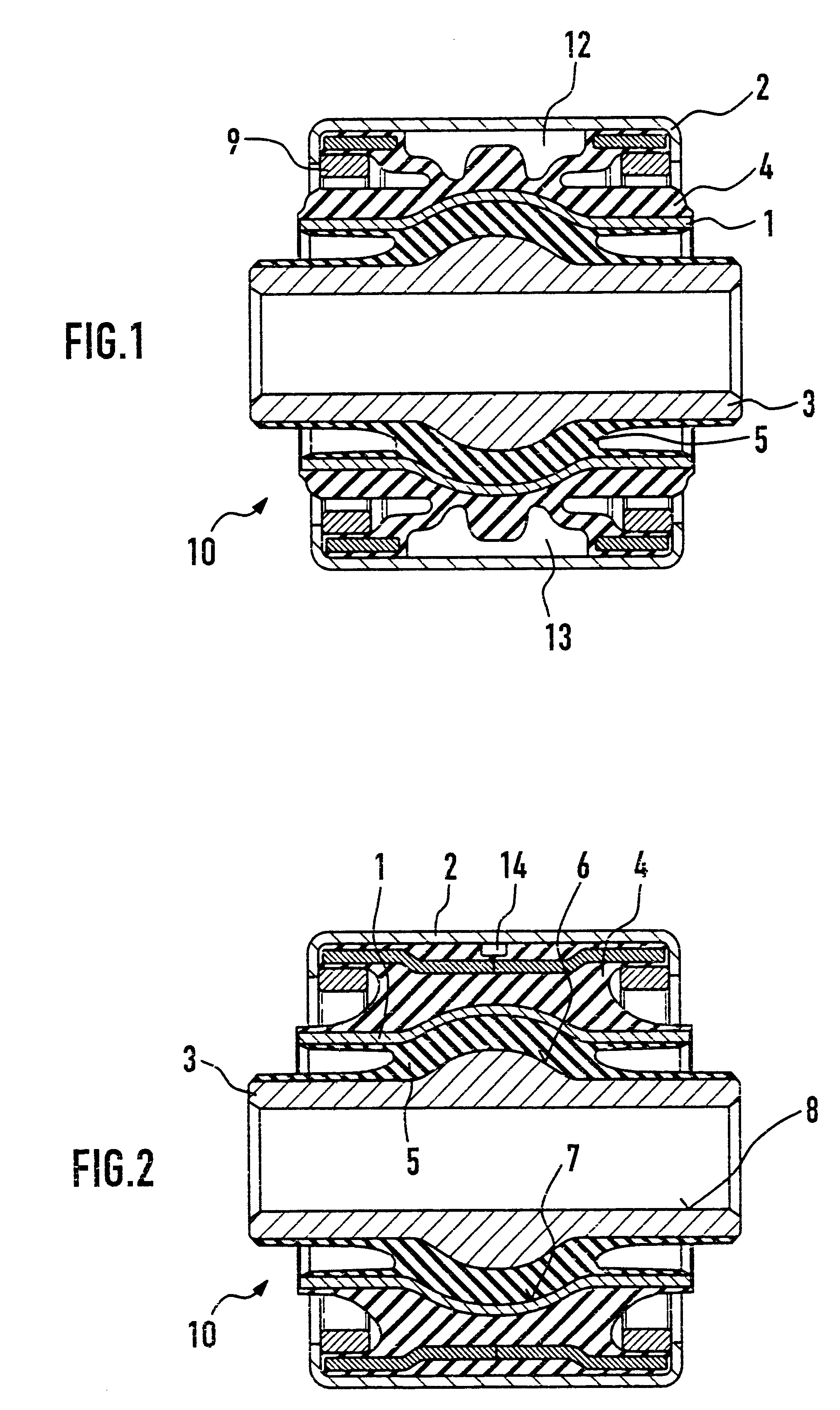
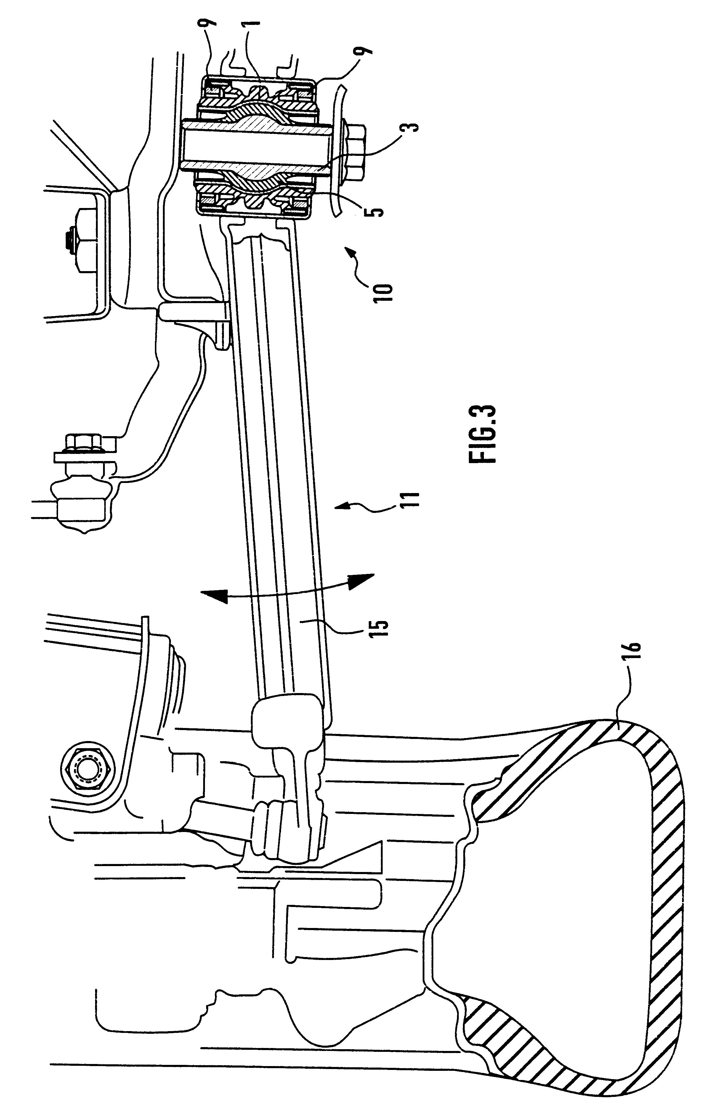
The rubber bearing shown in FIGS. 1 and 2 consists essentially of the inner tubular part 1, the outer tubular part 2, and a rubber part 4, located between the other two parts. Chambers 12, 13, which are filled with damping medium, are provided in the rubber part 4. These chambers exert a hydraulic damping effect in the axial direction, in that under certain conditions damping fluid flows from the chamber 12 via at least one damping channel 14 to the chamber 13 or vice versa. The external areas of the rubber part 4 facing in the axial direction are supported both on the inner part 1 and on the outer part 2, so that axial and radial movements can be executed, although cardanic movements can be absorbed to only a limited extent.

Between the inner part 1 and the additional tubular part 3, an elastic element 5 is provided, so that an additional conventional rubber bearing is formed in this area. So that cardanic movements can be executed easily, the outside surface of the additional tubul...


PUM


Abstract

Hydraulically damping rubber bearing consisting of an inner part, an outer part a certain distance concentrically or eccentrically outside the inner part, and a rubber part between the inner part and the outer part, in which rubber part at least one damping medium-filled chamber is provided. A certain distance concentrically inside the inner part, another tubular part is provided, part of the outside surface of this tubular part and part of the inside surface of the inner part being at least partially spherical, an elastic element being provided between these two spherical areas.

Description

1. Field of the InventionThe invention pertains to a hydraulically damping rubber bearing consisting of an inner part, an outer part a certain distance concentrically or eccentrically outside the inner part, and a rubber part held between the other two parts, at least one damping medium-filled chamber being provided in the rubber part.2. Description of the Related ArtRubber bearings which consist of an inner part, an outer part a certain distance concentrically or eccentrically outside the inner part, and a rubber part between the other two parts, in which at least one damping medium-filled chamber is provided, are already known (e.g., GB 2 342 422). In this rubber bearing, the inner or outer part work together with a tubular component and an additional elastic rubber part to form an additional bearing, which works either in parallel or in series with the first bearing. In a rubber bearing of this type, each of the two individual rubber bearings has different tasks to fulfill; by fi...

Claims


Application Information

Patent Timeline
Patent Type & Authority Patents(United States)
IPC IPC(8): B60G7/02F16F1/387F16F1/393F16F13/04F16F1/38F16F13/14
CPCB60G7/02F16F1/387F16F1/393F16F13/14B60G2200/142B60G2204/1432B60G2204/4104B60G2204/416
Inventor MAYERBOCK, WILHELMFRISCH, STEPHAN
Owner MANNESMANN BOGE
Why Eureka
Try Eureka