Adaptive liquid crystal lenses

a liquid crystal lens and liquid crystal technology, applied in the field of adaptive liquid crystal lenses, can solve the problems of ineffectiveness, and inability to adjust mechanical movements, and achieve the effect of sharp and clean images

Active Publication Date: 2005-02-22
UNIV OF CENT FLORIDA RES FOUND INC
View PDF10 Cites 185 Cited by
  • Summary
  • Abstract
  • Description
  • Claims
  • Application Information

AI Technical Summary

Benefits of technology

The third objective of the present invention is to produce an adaptive nematic LC device capable of providing a sharp, clean image.
The fourth objective of the present invention is to provide a method for making a variety of adaptive lenses, such as positive lens, polarizaton independent lens, negative lens and Fresnel lens that are continuously tunable.

Problems solved by technology

Adjustments accomplished with mechanical movement are inherently bulky and inefficient.
Due to the non-uniform LC cell gap, LC alignment along the inner convex surface becomes worse; thus, light is scattered by the LC layer.
The demerits of this kind of lens are that the operating technique is complicated, and there is light diffraction due to the grating-like electrode.

Method used


Image

  • Adaptive liquid crystal lenses
  • Adaptive liquid crystal lenses
  • Adaptive liquid crystal lenses

Examples


example 1

Positive Lens (Method 1)

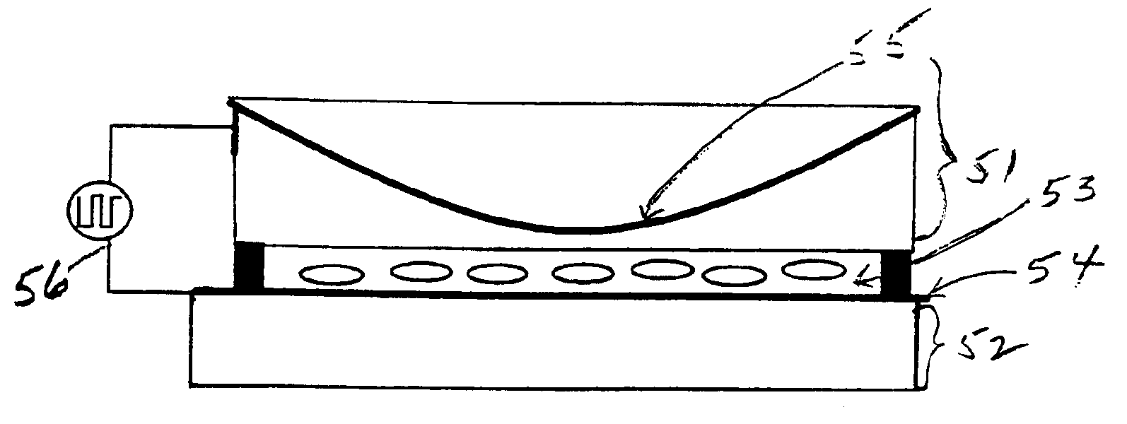
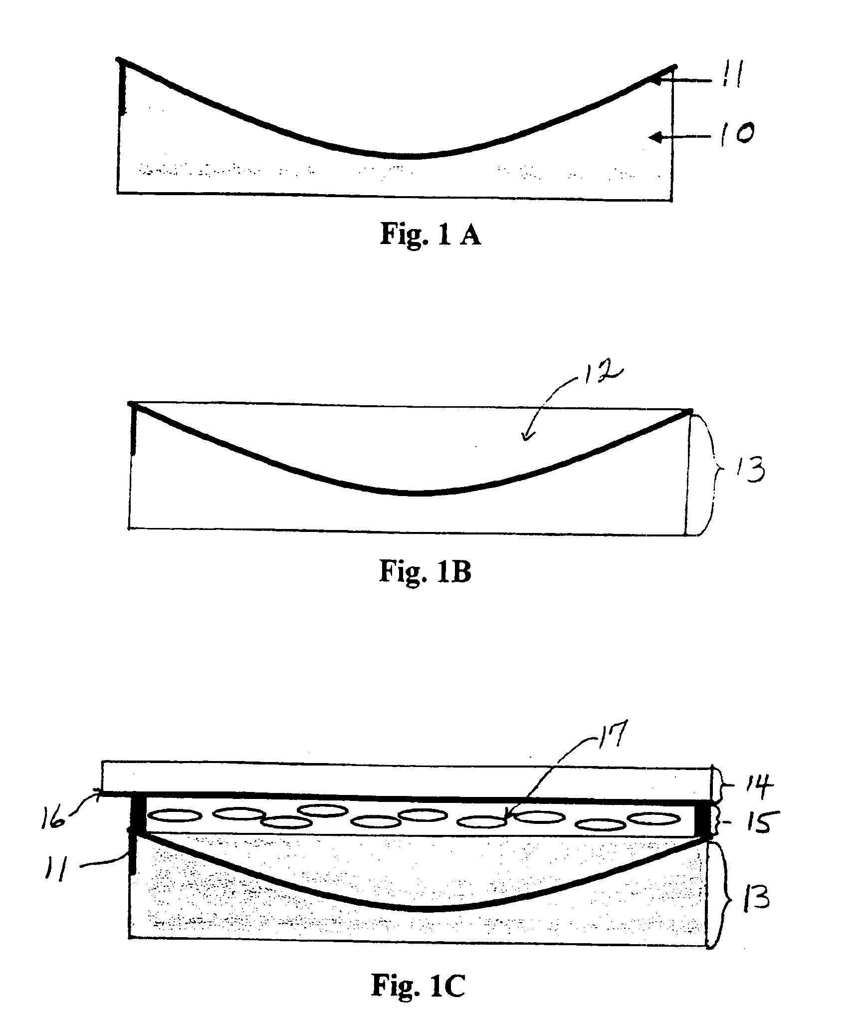
FIGS. 1A-1C show the fabrication process for a positive lens. The concave surface of a lens 10 is coated with a transparent electrode 11, such as, indium-tin-oxide (ITO), as shown in FIG. 1A. Then, the concave valley 12 is filled with the same material of the lens or polymer to form a planar substrate 13, as shown in FIG. 1B. Depending upon the refractive index of the glass or polymer substrate, many types of transparent materials, such as UV curable pre-polymer NOA65, NOA81 available from Norland Optical Adhesives, Edmund Industrial Optics, 101 East Gloucester Pike, Barrington N.J., 08007-1380, NOA65: L36-426, NOA81: L 36-428 or thermal cured polymer, or other similar materials can be chosen.

After filling the concave valley with transparent material, the planar substrate 13 is combined with another planar substrate 14 to confine the liquid crystal (LC) layer 15. The inner surface of substrate 14 is also coated with a transparent electrode 16. Both inner surf...

example 2

Positive Lens (Method 2)

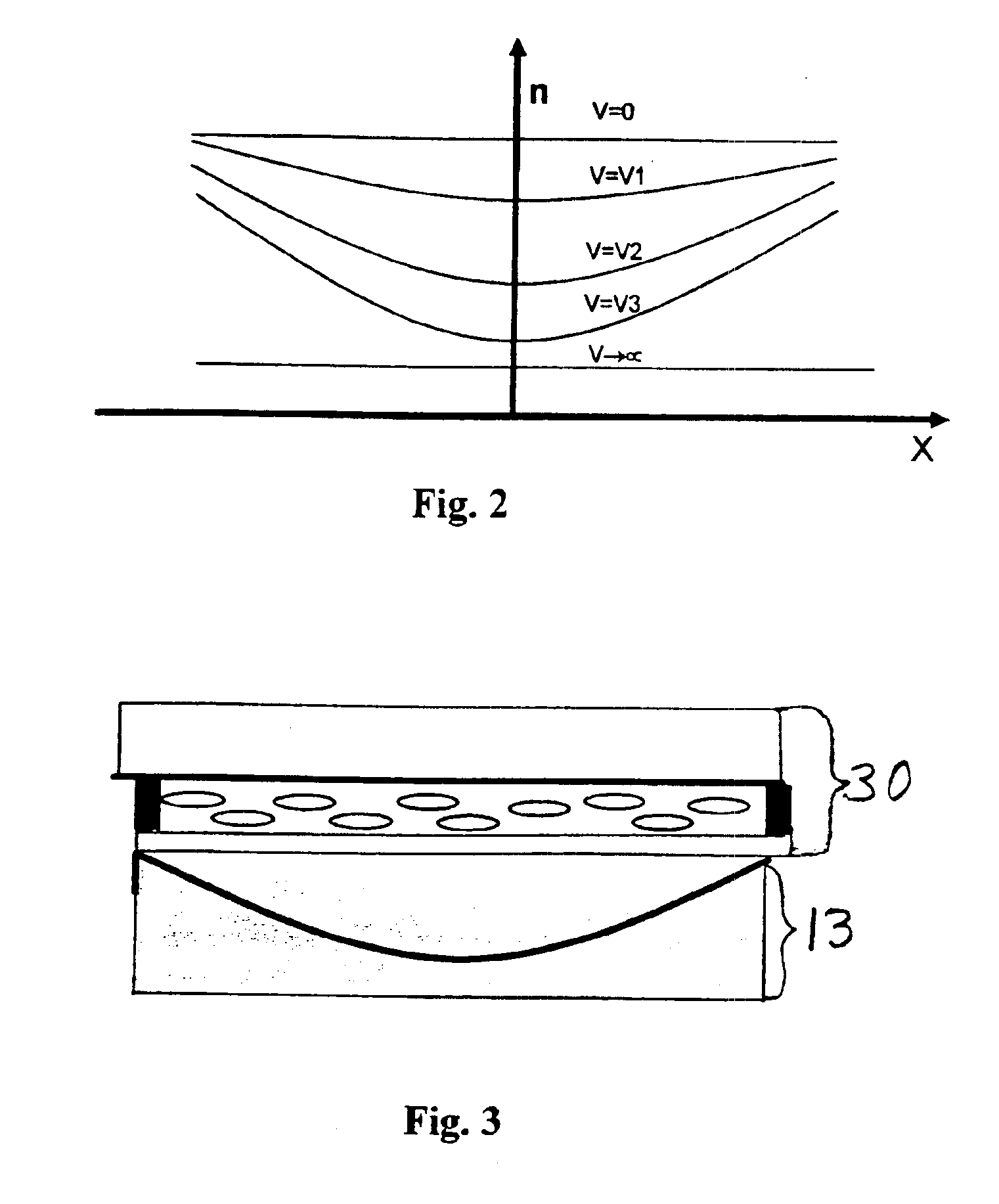
To simplify the lens fabrication processes, one can use a planar substrate 13 as shown in FIG. 1B to combine with a prepared LC cell 30, as shown in FIG. 3. Thus, to form a positive lens, a planar substrate having a concave lens surface with curved or concave electrode is positioned below the homogeneous nematic LC cell.

example 3

Polarization Independent Positive LC Lens

Using two concave lenses 41 and 42, and the similar fabrication processes as shown in FIG. 1, a first planar substrate 43, and a second planar substrate 44, are placed in a parallel arrangement with each having a spherical electrode layer 45 and 46, as shown in FIG. 4. The first and second planar substrates comprise spherical or curved electrodes positioned to form a concave mirror image. Two homogeneous LC layers 47 and 48 in orthogonal alignment are positioned between the first and second planar substrates. If the top LC layer 47 causes the extraordinary ray to change focus, then the bottom LC layer 48 will change the focus of the ordinary ray. Thus, this kind of lens is polarization independent. It is highly desirable to have polarization independent lens. Otherwise, the lens needs to use a linear polarizer, which would reduce the transparency of the lens by at least 50%. There is a middle substrate 49 made of transparent material, as show...


PUM

PropertyMeasurementUnit
transparencyaaaaaaaaaa
voltageaaaaaaaaaa
focal lengthaaaaaaaaaa

Abstract

An adaptive optical lens device, system and method of using the same is composed of at least two planar substrates and at least one homogeneous nematic liquid crystal (LC) layer. One planar substrate has a spherical or annular ring-shaped Fresnel grooved transparent electrode within it, the other has a transparent electrode coated on its inner surface. The thickness of the LC layer is uniform. When a voltage is applied across the LC layer, a centro-symmetrical gradient distribution of refractive index within LC layer will occur. Therefore, the LC layer causes light to focus. By controlling the applied voltage, the focal length of the lens is continuously tunable.

Description

This invention relates to an adaptive optical lens system, in particular to an adaptive liquid crystal lens, device, system and method for making the same wherein the focal length of the lens is continuously tunable.BACKGROUND AND PRIOR ARTA large birefringence and a low control voltage distinguish nematic liquid crystals (LCs) from other electro-optical materials. For a lens based on LC materials, a voltage is employed traditionally to vary its focus. Much of the past work on adaptive nematic LC lenses has focused on the lens structure, the focal length of the lens and the ability to tune the lens. One of the fundamental parameters describing a lens is its focal length. For virtually all lenses, the focal length is a static parameter, which means that, once the lens is constructed, the focal length is set. For a variable focal length to be obtained, usually a group of lenses, having separation distances between the lenses, is adjusted mechanically. Adjustments accomplished with mec...

Claims


Application Information

Patent Timeline
Patent Type & Authority Patents(United States)
IPC IPC(8): G02B3/14G02B3/12G02F1/13G02F1/1343G02F1/29
CPCG02B3/14G02F1/29G02F1/134309G02F2001/294G02F1/294
Inventor REN, HONGWENFAN, YUN-HSINGWU, SHIN-TSON
Owner UNIV OF CENT FLORIDA RES FOUND INC
Why Eureka
Try Eureka