Configuration marker design and detection for instrument tracking

a technology of configuration markers and positioning markers, applied in the field of configuration marker design and detection of instrument tracking, can solve the problems of affecting accuracy, kinematics estimated pose may not be very accurate, end effectors may become difficult to see, etc., and achieve accurate and reliable tool tracking, accurate and reliable image processing, and effective and reliable image-derived tool pose estimation

Active Publication Date: 2010-07-01
INTUITIVE SURGICAL OPERATIONS INC
View PDF41 Cites 182 Cited by
  • Summary
  • Abstract
  • Description
  • Claims
  • Application Information

AI Technical Summary

Benefits of technology

[0015]In accordance with embodiments, improved systems, methods, and tools for performing 3-D tool tracking using image-derived data from one or more tool located reference features are provided. The use of one or more reference features can provide for improved image-derived tool pose estimation by supplying one or more features that can be more reliably imaged and processed. Effective and reliable image-derived tool pose estimation can be particularly useful during minimally-invasive surgery, where accurate and reliable tool tracking can provide a number of advantages, such as to provide assistance to a Surgeon in locating an occluded or out-of-view tool. However, it is appreciated that the disclosed systems, methods, and tools can be used in a wide variety of applications, both inside and outside a human body, as well as in non-surgical tool tracking applications. In general, accurate information of a tool's 3-D pose is important for a number of image-guided and user interface applications.

Problems solved by technology

During the surgical procedure, however, the surgeon may manipulate the tool so that its end effector is moved outside of the endoscope's field of view, or the end effector may become difficult to see due to occlusion by fluids or other intervening objects.
While kinematics joint data are usually available at a very high update rate, a kinematics estimated pose may not be very accurate due to error accumulation at each joint, with errors in joints located farther away from the tool having a greater impact on accuracy.
However, the optical tracker requires a dedicated stereo camera and dedicated lighting, which take space in an already crowded operating room.
Attaching such optical trackers also reduces the range of motion of the robotic arms due to the potential for collision.
There can also be some level of error that results from propagating the 3-D pose to the surgical tool tip.
Additional problems include: the extra space required, limited visibility range, the added hardware setup in the operating room, and cost.
For example, most surgical instruments have metal parts that can cause distortion, which can vary in time due to changes in distances between an electromagnetic tracker attached to one tool tip and metal components of an adjacent surgical tool.
An electromagnetic tracker also involves extra cost.
Computing the 3-D pose of a rigid body with respect to a camera is a well-studied problem in computer / robot vision.
However, a number of factors can hamper the ability to obtain an image-derived tool pose estimation.
Some of the factors that may prevent the extraction of features include: occlusion of the features by anatomical structure or other instruments, degenerated image quality caused by fast instrument or camera motion (i.e., motion blur), adverse lighting conditions (e.g., saturation when the light is too strong, lack of contrast when the light is too weak, strong specularity due to the relative geometric configurations of the light source, instrument, and imaging device), and complex background clutter.

Method used


Image

  • Configuration marker design and detection for instrument tracking
  • Configuration marker design and detection for instrument tracking
  • Configuration marker design and detection for instrument tracking

Examples


Embodiment Construction

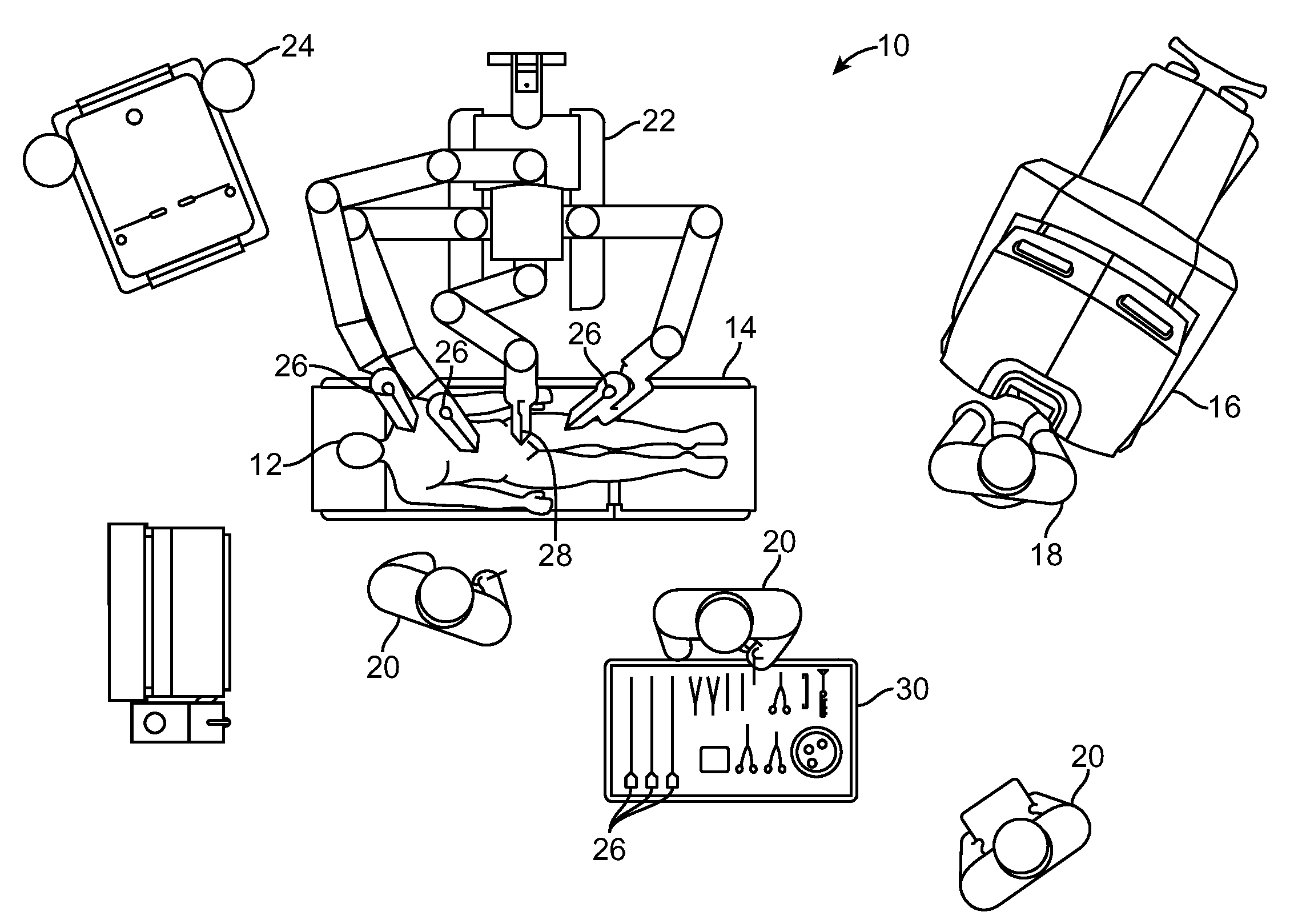
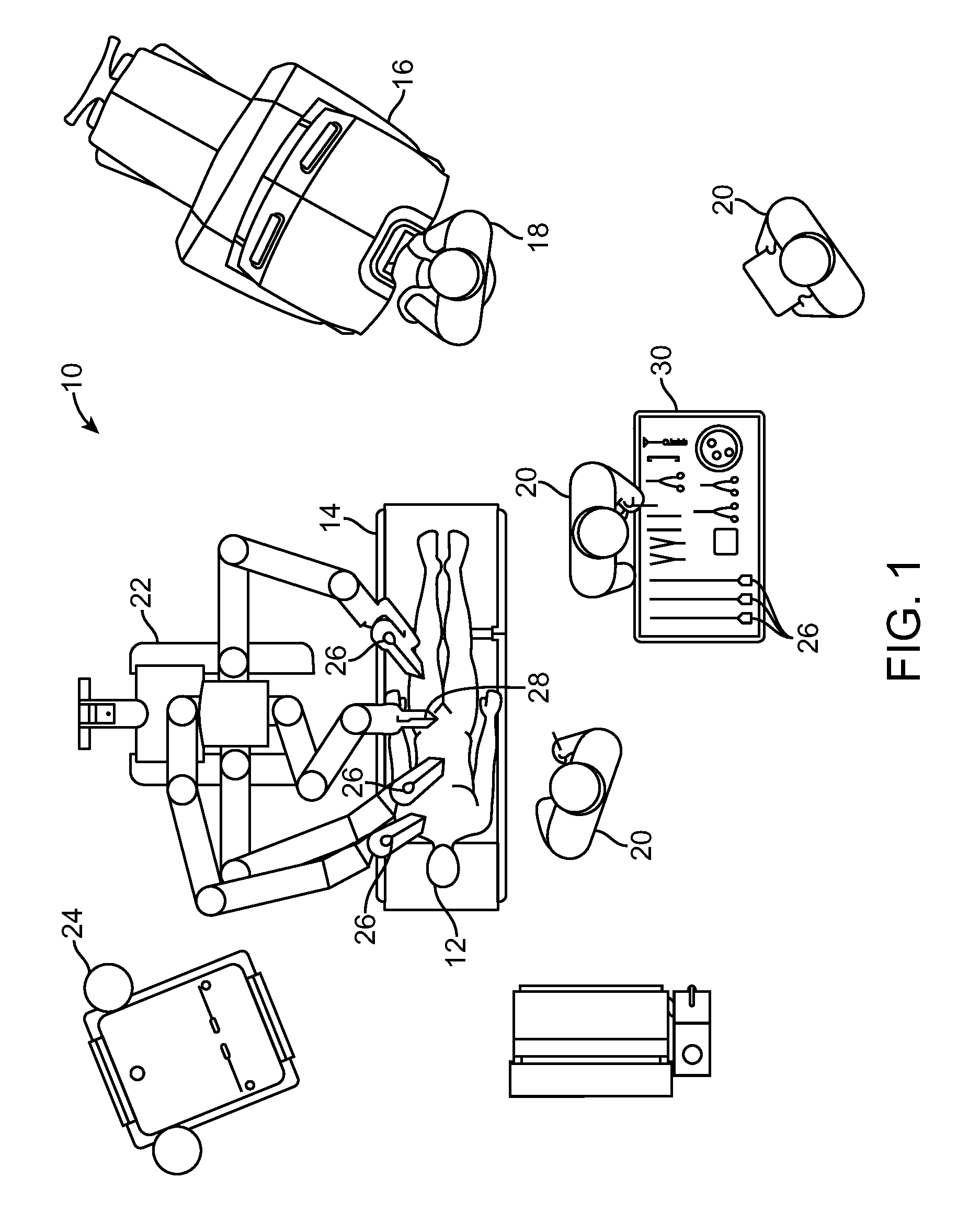
[0075]In accordance with embodiments, improved methods and systems are provided for three-dimensional (3-D) object tracking using image-derived data from one or more object located reference features. Such methods and systems can be particularly advantageous when employed for tracking surgical tools during minimally-invasive robotic surgery.

[0076]The following terms are used herein. A “feature” is a general term used to denote whatever useful information can be extracted from an image. A “primitive feature” is used to denote small or simple features that can be extracted locally from an image (e.g., a salient blob, a small circle, a dot, a bar, etc.). A primitive feature is in contrast with a “composite feature”, where multiple primitive features are used to create a composite feature. A “marker” is some discernible (typically visible) pattern used for locating an object or computing the pose of an object. A marker can be composed of multiple primitive features. A “tool state” is a ...


PUM


Abstract

The present disclosure relates to systems, methods, and tools for tool tracking using image-derived data from one or more tool located reference features. A method includes: directing illuminating light from a light source onto a robotic surgical tool within a patient body, wherein the tool includes a plurality of primitive features having known positions on the tool, and wherein each feature includes a spherical reflective surface; capturing stereo images of the plurality of primitive features when the tool is within the patient body, wherein the stereo images are captured by an image capture device adjacent the illumination source so that the illumination light reflected from the imaged primitive features toward the image capture device substantially aligns with spherical centers of the surfaces of the imaged primitive features, and determining a position for the tool by processing the stereo images so as to locate the spherical centers of the imaged primitive features by using the reflected light.

Description

RELATED APPLICATION[0001]This non-provisional application claims the benefit under 35 U.S.C. §119(e) of provisional U.S. Pat. App. No. 61 / 203,975 (filed Dec. 31, 2008), which is incorporated herein by reference.[0002]This application is related to non-provisional U.S. patent application Ser. No. ______ (concurrently filed) [Attorney Docket No. ISRG 01480 / US, entitled “Fiducial Marker Design and Detection for Locating Surgical Instrument Images”] and to provisional U.S. Pat. App. No. 61 / 204,084 (filed Dec. 31, 2008), both of which are incorporated herein by reference.BACKGROUND[0003]Minimally-invasive surgical techniques are aimed at reducing the amount of extraneous tissue that is damaged during diagnostic or surgical procedures, thereby reducing patient recovery time, discomfort, and deleterious side effects. As a consequence, the average length of a hospital stay for standard surgery may be shortened significantly using minimally-invasive surgical techniques. Also, patient recover...

Claims


Application Information

Patent Timeline
Patent Type & Authority Applications(United States)
IPC IPC(8): A61B19/00A61B5/05
CPCA61B2090/3983A61B2034/102A61B34/30A61B34/20A61B90/94A61B2090/371A61B2034/2065A61B34/37G06T2207/30004H04N23/45
Inventor ZHAO, TAOZHAO, WENYINOWLIN, WILLIAM C.
Owner INTUITIVE SURGICAL OPERATIONS INC
Why Eureka
Try Eureka