Drive belt for continuously variable transmission

a technology of continuously variable transmission and drive belt, which is applied in the direction of driving belt, v-belt, belt/chain/gearing, etc., can solve the problems of v-shaped block tilting, v-shaped block rotation, and the center plane of the v-shaped groove that occurs during the axial movement of the moveable flang

Inactive Publication Date: 2003-09-23
NISSAN MOTOR CO LTD
View PDF4 Cites 6 Cited by
  • Summary
  • Abstract
  • Description
  • Claims
  • Application Information

AI Technical Summary

Problems solved by technology

It has been discovered that in a V-belt continuously variable transmission, as described in the aforementioned publication, the displacement of the center planes of the V-shaped grooves that occurs during the axial movements of the moveable flanges do not match when moveable flanges are moved in the same axial direction during gear changing control.
Moreover, this transverse force causes the V-shaped blocks becomes tilted with respect to the pulleys, since the V-shape blocks are unable to maintain their parallel orientation with respect to the pulley axes.
However, the rigidity of the belt in the lengthwise direction (circumferential direction) would decline and there would be a higher likelihood of increased vibrations and / or derailing of the V-shaped blocks during rotation.

Method used


Image

  • Drive belt for continuously variable transmission
  • Drive belt for continuously variable transmission
  • Drive belt for continuously variable transmission

Examples


first embodiment

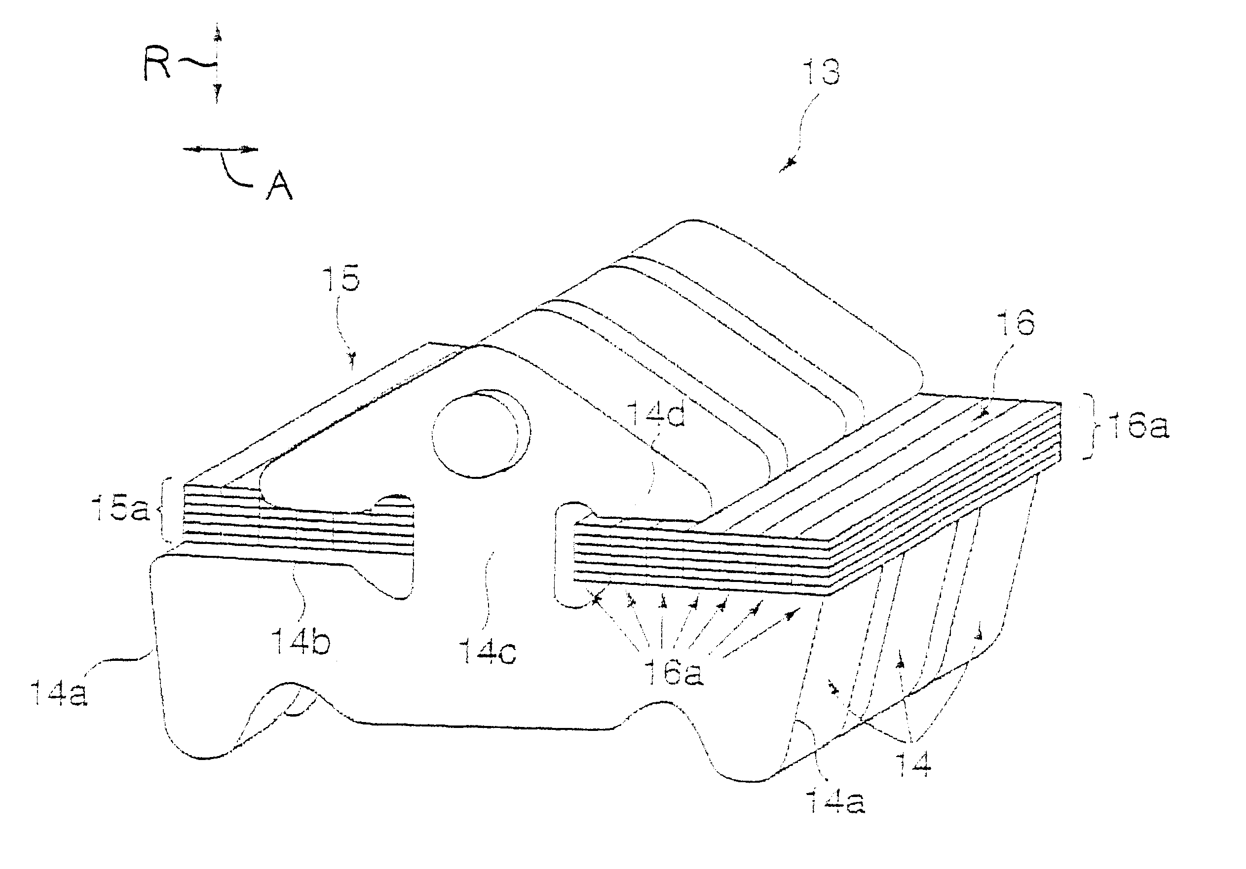
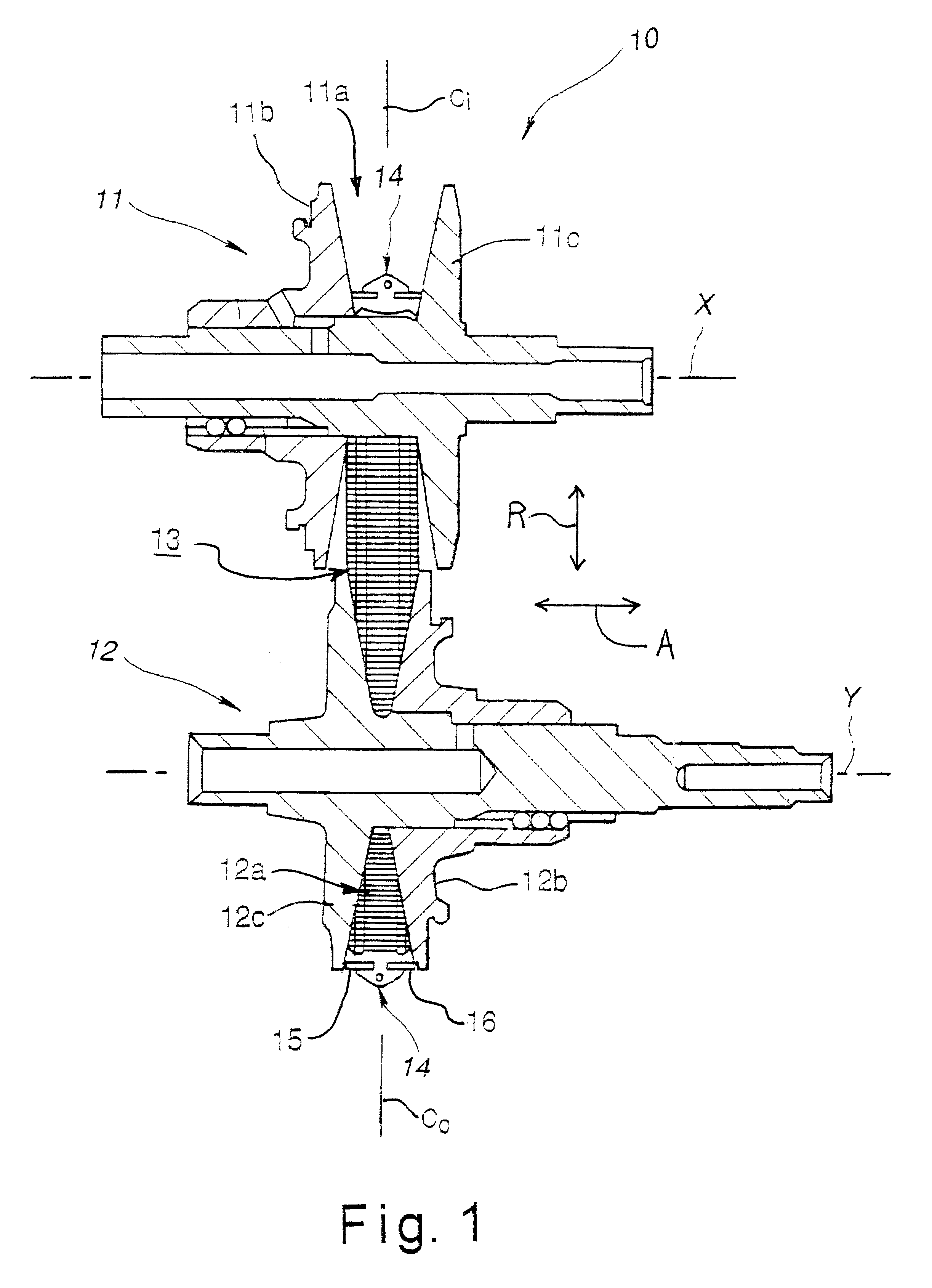
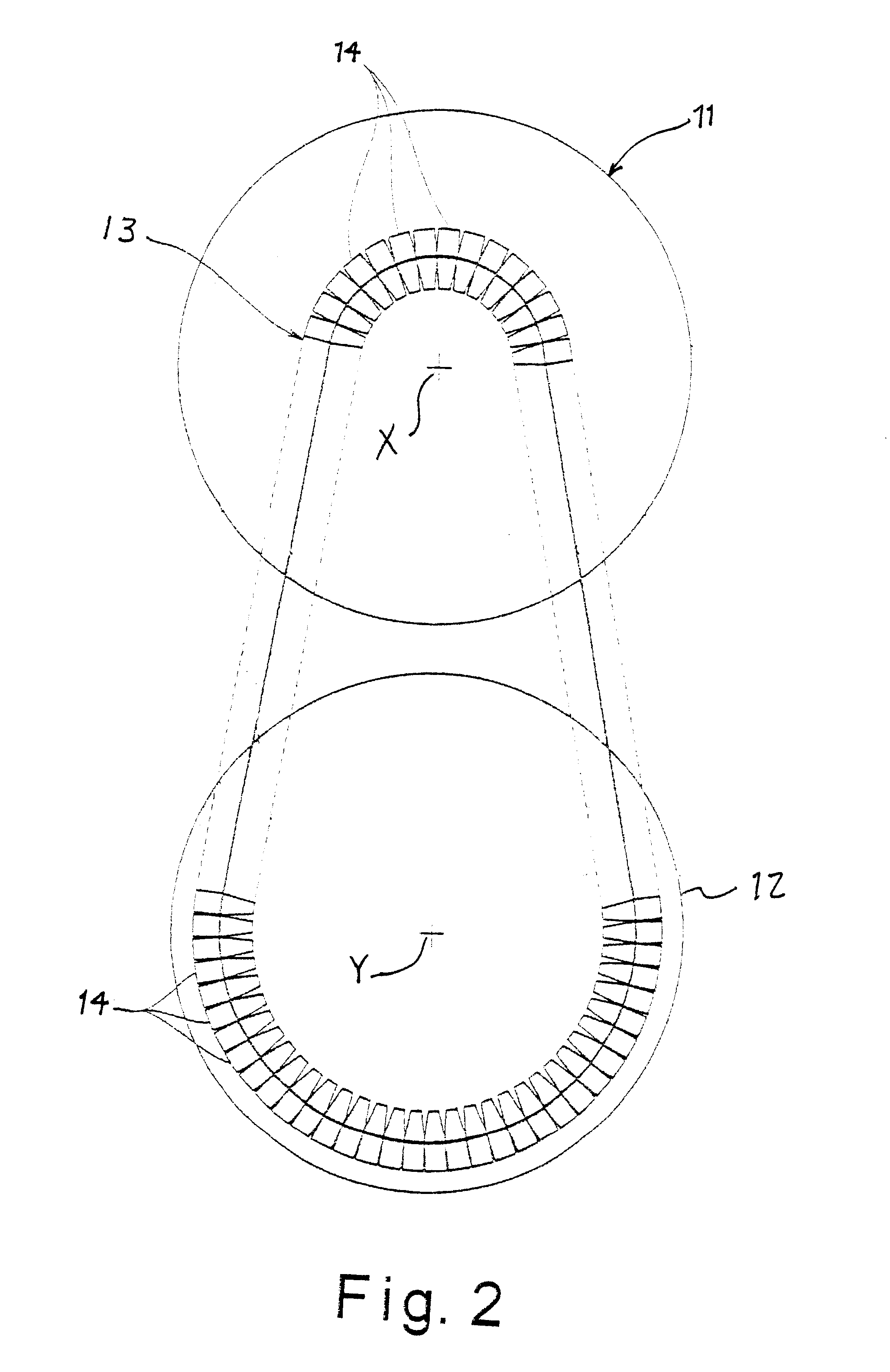
Referring initially to FIGS. 1-3, a belt driven type continuously variable transmission 10 is illustrated, which basically includes an input pulley 11, an output pulley 12 and a drive belt 13 in accordance with the present invention. The input pulley 11 is driven so as to rotate about a first axis X, while the output pulley 12 rotates about a second axis Y that is parallel to the first axis X. In this drive arrangement, the rotation of the input pulley 11 is transmitted to the output pulley 12 via the drive belt 13. The input pulley 11 has a V-shaped groove 11a defined by a movable flange 11b and a stationary flange 11c. The output pulley 12 has a V-shaped groove 12a defined by a movable flange 12b and a stationary flange 12c. The widths of the V-shaped grooves 11a and 12a are independently varied in an axial direction A in a conventional manner such that continuously variable gear changing can be accomplished. During this transmission, the movable flanges 11b and 12b of the pulleys...

second embodiment

Referring now to FIG. 6, a portion of a drive belt 13' is illustrated in accordance with a second embodiment. In view of the similarity between the first and second embodiments, the descriptions of the parts of the second embodiment that are identical to the parts of the first embodiment may be omitted for the sake of brevity. The parts of the second embodiment that are substantially identical to the parts of the first embodiment will be given the same reference numeral but with a prime (') added thereto.

Similar to the first embodiment, the assembled drive belt 13' is preferably a power transmission V-belt that has a plurality of successively arranged V-shaped blocks 14' connected together by a pair of endless bands 15' and 16' to from a continuous loop. Thus, the V-shaped blocks 14' are successively arranged in an endless shape so as to form a V-belt. Each of the V-shaped blocks 14' has a pair of slanted end surfaces 14a' that frictionally contact the side walls of the V-shaped gro...


PUM


Abstract

A drive belt for use in a continuously variable transmission has an endless carrier and a plurality of elements. The endless carrier has a plurality of endless metal belts with plank-shaped cross sectional shapes laminated together in both radial and axial directions to form ring aggregates. The ring aggregates reduce the rigidity of the endless carrier in the axial direction and increase the allowable axial deflection endless. Thus, when off-centering occurs, the entire V-belt does not become slanted with respect to a line perpendicular to the rotational axes of the pulleys and the V-shaped blocks can be prevented from becoming tilted with respect to the pulley. As a result, the durability of the pulleys and V-shaped blocks can be improved. The entire V-belt becomes slanted when off-centering occurs in a V-belt continuously variable transmission.

Description

1. Field of the InventionThe present invention relates to a drive belt for use in a V-belt continuously variable transmission. More specifically, the present invention relates to a drive belt that is capable of accommodating the off-centering of the pulleys in the axial direction.2. Background InformationAn example of a typical V-belt for a continuously variable transmission is shown in Japanese Laid-Open Patent Publication No. 8-21488. This V-belt continuously variable transmission basically includes an assembled power transmission V-belt that runs between the V-shaped groove of an input pulley and the V-shaped groove of an output pulley. The input pulley is driven so as to rotate about a first axis, while the output pulley rotates about a second axis that is parallel to the first axis. In this arrangement, the rotation of the input pulley is transmitted to the output pulley via the assembled power transmission V-belt. During this transmission, the movable flanges of both pulleys a...

Claims


Application Information

Patent Timeline
Patent Type & Authority Patents(United States)
IPC IPC(8): F16G5/00F16G5/16
CPCF16G5/16
Inventor KOYAMA, TAKAO
Owner NISSAN MOTOR CO LTD
Why Eureka
Try Eureka