Compact microchannel system

a microchannel system and compact technology, applied in the field of compact microchannel systems, can solve the problems of non-uniform fluid motion, non-uniform electrophoretic separation, and non-uniform dispersion, so as to reduce the minimum turn radius and reduce the minimum radius, without degrading the resolution of separation process

Inactive Publication Date: 2003-09-30
NAT TECH & ENG SOLUTIONS OF SANDIA LLC
View PDF11 Cites 74 Cited by
  • Summary
  • Abstract
  • Description
  • Claims
  • Application Information

AI Technical Summary

Benefits of technology

We find that a straight channel segment adjoining a turn significantly reduces the minimum turn radius, provided that the segment length is sufficient: some reduction in the minimum radius can be obtained even when the straight segment length is smaller than the turn radius. Folded separation columns containing straight channel segments may thus employ turns having radii smaller than the minimum radius for a spiral geometry, without degrading the resolution of separation processes.

Problems solved by technology

Although larger surface areas provide better separation between arrival times, the use of packing materials causes nonuniformity of the fluid motion.
Like electrochromatographic processes, electrophoretic separations may be severely degraded by diffusion or dispersion.
In the latter case, however, dispersion may arise not only from nonuniformity of the carrier fluid speed but may also arise directly from nonuniformity of the electric field across the column cross-section.
Although species motion in both electrophoretic and electroosmotic transport may be relatively free of both diffusive and dispersive spreading in straight tubes or channels having parallel walls, any local variation in the fluid speed or local field strength introduces dramatic skewing of an otherwise flat interface or species band.
Thus, an initially flat interface will be severely skewed in passing through a turn.
This restriction limits the separation between peaks traveling at different speeds and, so, limits the resolution of separation devices.
This spreading impairs performance in separation processes, as well as in routine sample transport where the integrity of a band or interface is desired.

Method used


Image

  • Compact microchannel system
  • Compact microchannel system
  • Compact microchannel system

Examples


Embodiment Construction

--Pleated and Coiled Columns

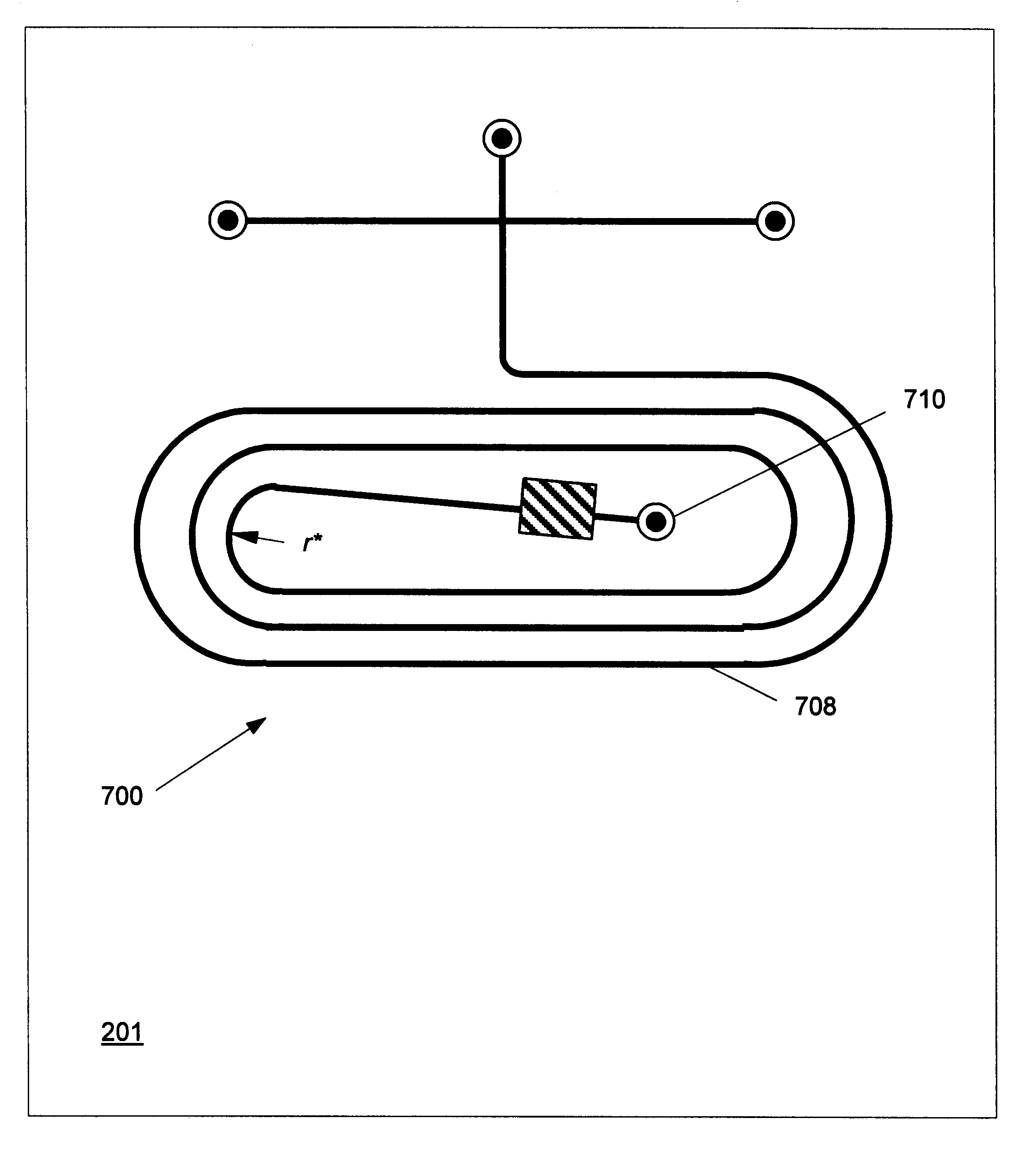
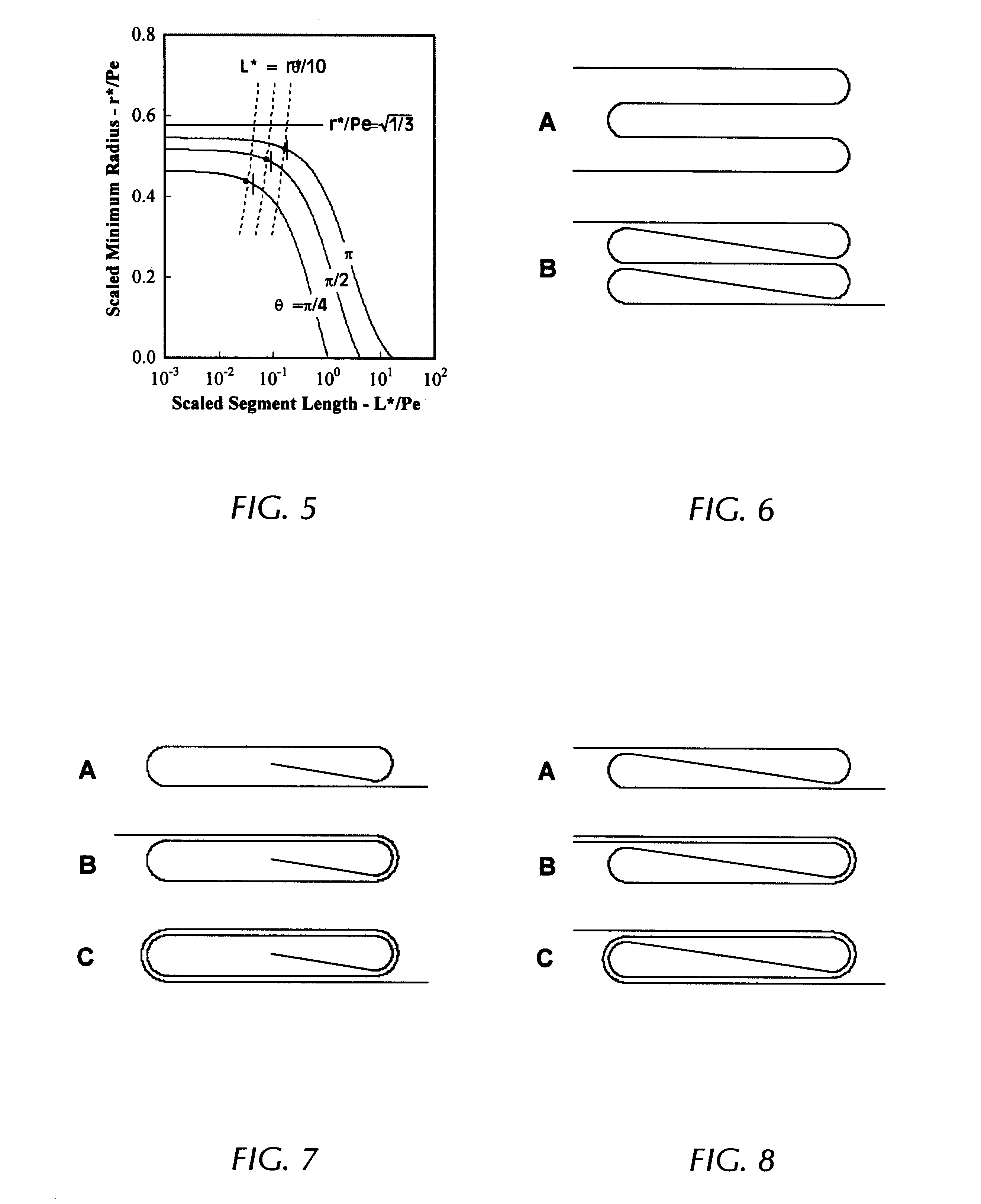
Both spiral and conventional folded columns offer advantages and drawbacks from a practical perspective. While spiral columns retain useful chip area in their interior, the minimum spiral radius may still be quite large for a high-performance column operating at high Peclet numbers. Such columns do not take advantage of the benefit of adjoining straight channel segments in reducing the minimum turn radius. Folded columns, on the other hand, can be constructed using relatively smaller turn radii when the straight channel segments are sufficiently long. Even so, conventional folded columns consisting of parallel straight segments joined by multiple turns make very poor use of available chip area. As shown in FIG. 6A, the spacing between the straight segments is twice the turn radius, and this may still be significant at high Peclet numbers. As a practical result, it is generally difficult to fold high-performance columns more than a few times using this con...


PUM

PropertyMeasurementUnit
lengthaaaaaaaaaa
lengthaaaaaaaaaa
Peclet numberaaaaaaaaaa

Abstract

The present invention provides compact geometries for the layout of microchannel columns through the use of turns and straight channel segments. These compact geometries permit the use of long separation or reaction columns on a small microchannel substrate or, equivalently, permit columns of a fixed length to occupy a smaller substrate area. The new geometries are based in part on mathematical analyses that provide the minimum turn radius for which column performance in not degraded. In particular, we find that straight channel segments of sufficient length reduce the required minimum turn radius, enabling compact channel layout when turns and straight segments are combined. The compact geometries are obtained by using turns and straight segments in overlapped or nested arrangements to form pleated or coiled columns.

Description

BACKGROUND OF INVENTIONMicrochannel devices are finding increased use in the separation, identification and synthesis of a wide range of chemical and biological species. Employing transverse channel dimensions in the range from a few microns to about one millimeter, such systems may permit the miniaturization and large-scale integration of many chemical processes in a manner analogous to that already achieved in microelectronics. Applications for microchannel devices now under development include such diverse processes as DNA sequencing, immunochromatography, the identification of explosives, identification of chemical and biological warfare agents, and the synthesis of chemicals and drugs.In addition to the potential for large-scale integration, the small physical scales of microchannel devices offer a few inherent advantages over their traditional macro-scale counterparts. Traditional chromatographic separations are usually performed in packed columns. The role of the packing is t...

Claims


Application Information

Patent Timeline
Patent Type & Authority Patents(United States)
IPC IPC(8): G01N30/00G01N30/60G01N30/38
CPCG01N30/6095G01N30/38G01N30/6086
Inventor GRIFFITHS, STEWART
Owner NAT TECH & ENG SOLUTIONS OF SANDIA LLC
Why Eureka
Try Eureka