Automatic brake booster

a technology of automatic brakes and boosters, which is applied in the direction of automatic initiation, brake systems, transportation and packaging, etc., can solve the problems of large variation in magnitude, difficult to achieve precise control, and instability of reaction, so as to avoid time lag in reaction transmission, minimize the variation in reaction, and improve accuracy

Inactive Publication Date: 2003-10-21
DIESEL KIKI CO LTD
View PDF3 Cites 7 Cited by
  • Summary
  • Abstract
  • Description
  • Claims
  • Application Information

AI Technical Summary

Benefits of technology

With the arrangement of the invention as mentioned above, when the solenoid is energized to deliver a brake output, the acting force which results from the pressure differential between the pressure in the constant pressure chamber and the pressure in the variable pressure chamber acts as a reaction on the solenoid plunger, whereby the transmission path from the energization of the solenoid to the transmission of the reaction to the solenoid plunger is simplified, minimizing a variation in the reaction and avoiding a time lag in the transmission of the reaction. Consequently, a brake output when operating as an automatic brake can be controlled with a better accuracy as compared with a conventional automatic brake booster.

Problems solved by technology

However, when an arrangement is employed in which a brake reaction is transmitted to the solenoid plunger, as a brake output is delivered by energizing the solenoid, a transmission path becomes complicated for the solenoid plunger to be operated once and the reaction therefrom be transmitted to the solenoid plunger, resulting in a large variation in the magnitude of reaction which is transmitted to the solenoid plunger and leading to instability of the reaction.
This makes it difficult to achieve a precise control by controlling the current or voltage applied to the solenoid in order to control the brake output.

Method used


Image

  • Automatic brake booster
  • Automatic brake booster
  • Automatic brake booster

Examples


second embodiment

This second embodiment is also capable of achieving a similar functioning and effects as in the first embodiment.

Third Embodiment

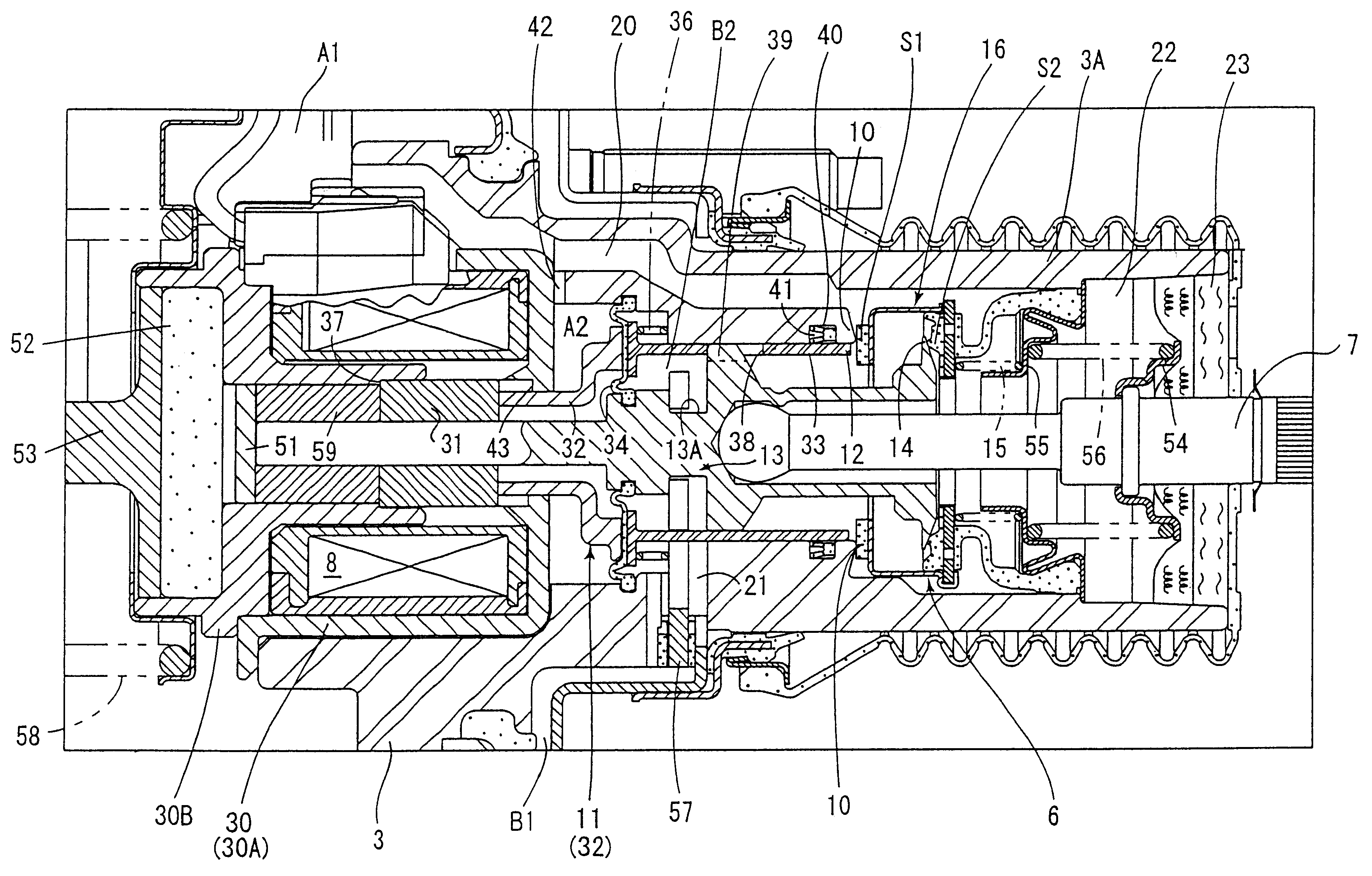
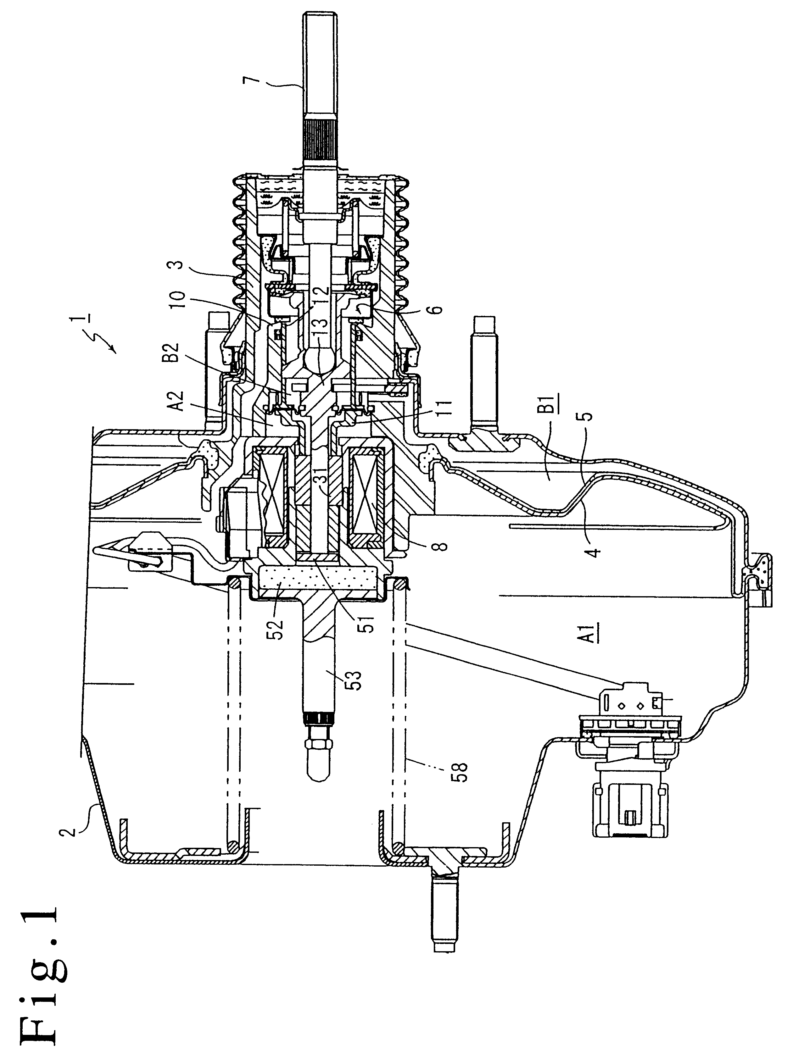
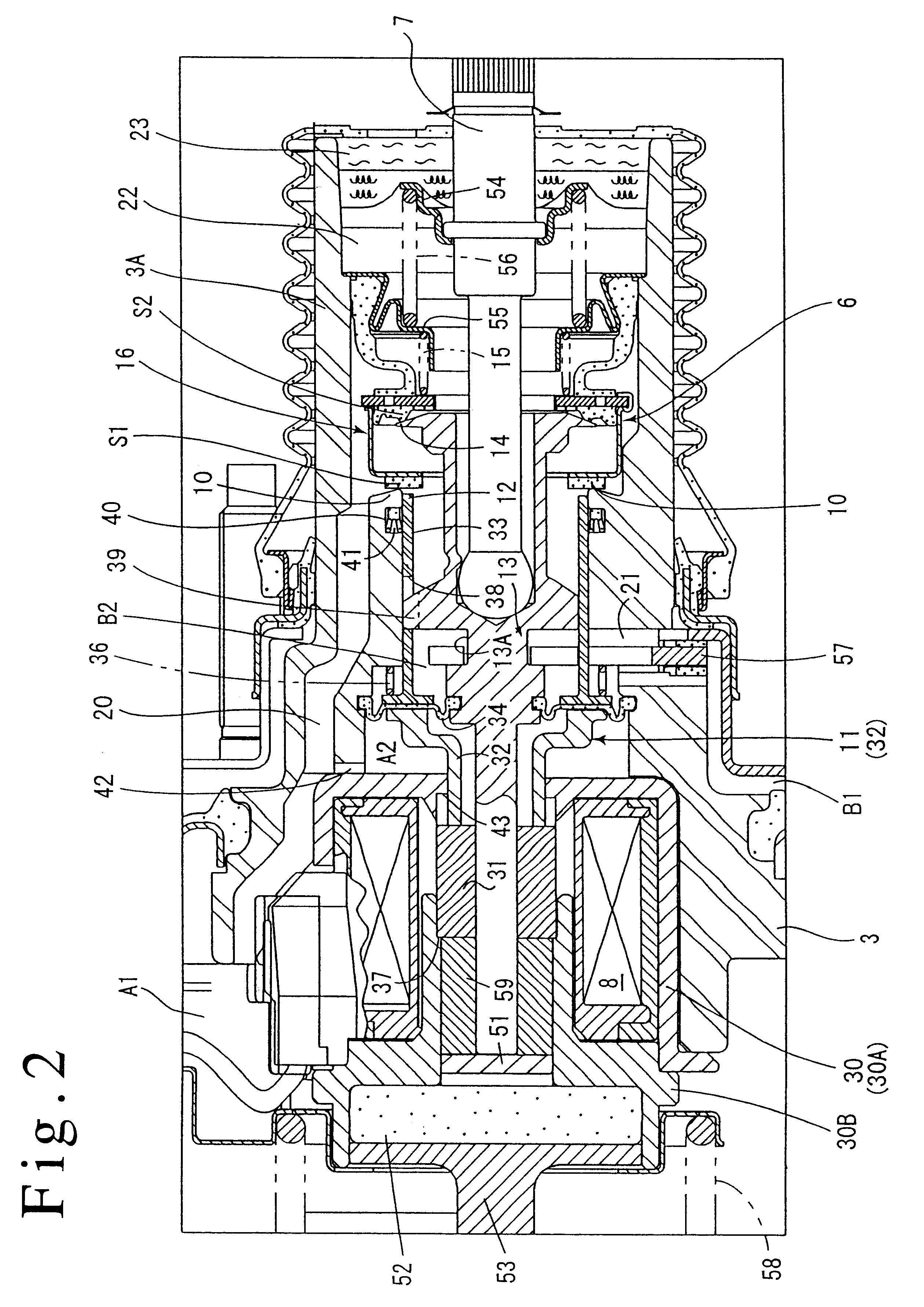
FIG. 4 shows a third embodiment of the present invention where a valve plunger 113 comprises a plurality of members which are axially disposed and a second vacuum valve seat member 111 also comprises a plurality of members. Such an arrangement facilitates an assembly of the valve plunger 113 and a diaphragm 134 which forms the pressure responsive area within a valve body 103.

Specifically, the valve plunger 113 comprises a rearwardly located plunger member 113a, a forwardly located rod member 113b, and an annular member 113c and a connecting member 113d which are used to connect a diaphragm 134 to the rear end of the rod member 113b.

An atmosphere valve seat 114 is formed on the rear end face of the rear plunger member 113a, which is formed with a bottomed opening in which an input shaft 107 is fitted. Toward the front end, the plunger member 113a is formed ...

third embodiment

Operation of Third Embodiment

In the inoperative condition shown in FIG. 4, the solenoid 108 is not energized by the controller, and under this condition, the second vacuum valve seat member 111 and the solenoid plunger 131 are maintained in their inoperative positions shown, and the second vacuum valve seat 112 is located forwardly of the first vacuum valve seat 110.

On the other hand, the key member 157 is in abutment against the shell 102 and thus its retracting movement is limited. The valve body 103 abuts against the key member 157, and thus its retracting movement is also limited. Under this condition, the valve element 116 is seated on the atmosphere valve seat 114 which forms the valve mechanism 106 to interrupt a communication between the variable pressure chambers B1 and B2 with the atmosphere, and is removed from the first vacuum valve seat 110 and the second vacuum valve seat 112 to allow a communication between the constant pressure chamber A1 and the variable pressure ch...


PUM


Abstract

An automatic brake booster 1 includes a solenoid 8 which causes a back- and forth movement of a solenoid plunger 31 to switch a valve mechanism 6. A second vacuum valve seat member 11 including a second vacuum valve seat 12 which is juxtaposed with a first vacuum valve seat 10 on a valve body 3 and a pressure responsive area 34 subject to a pressure of a variable pressure chamber and a pressure of a constant pressure chamber is slidably mounted on the valve body. The effect of the pressure differential acting upon the pressure responsive area is balanced with the force resulting from the excitation of the solenoid plunger 31 to deliver a brake output which corresponds to the force. The invention enables a high accuracy control of a brake output during an automatic brake operation.

Description

The present invention relates to an automatic brake booster which is used in a brake of an automobile or the like, and more particularly, to an improvement of the valve mechanism thereof.DESCRIPTION OF THE PRIOR ARTAn automatic brake booster is known in the art which comprises a valve body slidably disposed within a shell, a power piston mounted on the valve body to partition the interior of the shell into a constant pressure chamber and a variable pressure chamber, a valve mechanism for supplying a fluid to or displacing it from the variable pressure chamber, an input shaft for switching the valve mechanism, and a solenoid which drives a solenoid plunger slidably mounted on the valve body back and forth to switch the valve mechanism, the valve mechanism including a first vacuum valve seat formed on the valve body, an atmosphere valve seat formed on the valve plunger which is coupled to the input shaft, and a valve element which becomes seated on the first vacuum valve seat and the ...

Claims


Application Information

Patent Timeline
Patent Type & Authority Patents(United States)
IPC IPC(8): B60T13/66B60T13/72B60T13/57B60T7/12B60T13/52
CPCB60T7/12B60T13/72B60T13/57B60T13/52
Inventor YAMAGA, HIROYUKIINOUE, HIDEFUMI
Owner DIESEL KIKI CO LTD
Why Eureka
Try Eureka