Detachable insulation wire-pressing element of a stapling device

a stapling device and detachable insulation technology, which is applied in the direction of nailing tools, nailing tools, clothes making applications, etc., can solve the problems of inconvenient actual operation, inability to mount utilizing the staple row 20 of wire at the outdoors, and inability to meet the needs of the customer

Inactive Publication Date: 2003-10-21
CHEN TUNG I
View PDF7 Cites 124 Cited by
  • Summary
  • Abstract
  • Description
  • Claims
  • Application Information

AI Technical Summary

Benefits of technology

Accordingly, it is an object of the present invention to provide a detachable insulation wire-pressing element of a stapling device, wherein the wire-pressing element is detachable from the stapling device, thereby the stapling device can be used at outdoors and indoors.
Yet another object of the present invention to provide a detachable insulation wire-pressing element of a stapling device, wherein the wire-pressing element has a wire-pressing section at the center of the element and the bottom face of the wire-pressing section is provided with a wire slot having an opening facing downward, the two sides of the wire-pressing section are respectively provided with a corresponding nailing hole, and the nailing hole is corresponding to a staple-impacting plate of the stapling device, thereby a wire-pressing element is formed. The stapling device can be used indoors and outdoors and provides convenient operation and the economic effectiveness of the stapling device is improved.

Problems solved by technology

The above mounting utilizing the staple row 20 of wire at outdoors may be damaged by weather factors or other factors.
Thus, it is inconvenient in actual operation.
At the same time, the staple body 45 on the wire-pressing seat 40 has to be one by one, inserted onto the wire-pressing seat 40 in the process of manufacturing, the speed of manufacturing is slow and the cost of manufacturing is high.
In view of the above, the indoor use and outdoor use stapling devices pose individual drawbacks, and the slots seats are different from each other.
Therefore, they cannot be used for both devices.
Therefore, it is a troublesome for the user in operating the stapling device.

Method used


Image

  • Detachable insulation wire-pressing element of a stapling device
  • Detachable insulation wire-pressing element of a stapling device
  • Detachable insulation wire-pressing element of a stapling device

Examples


Embodiment Construction

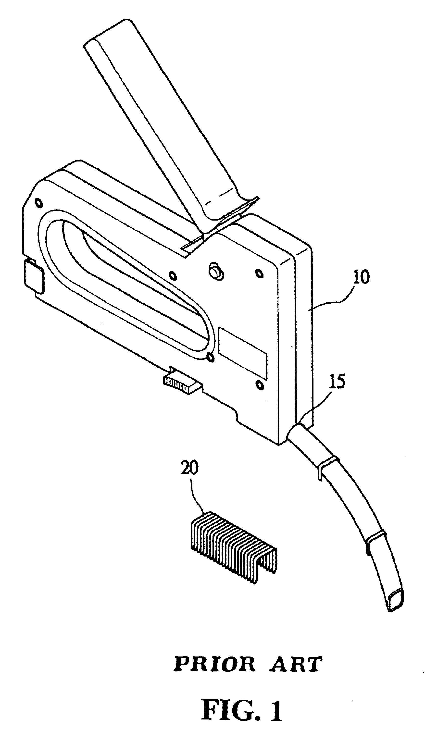
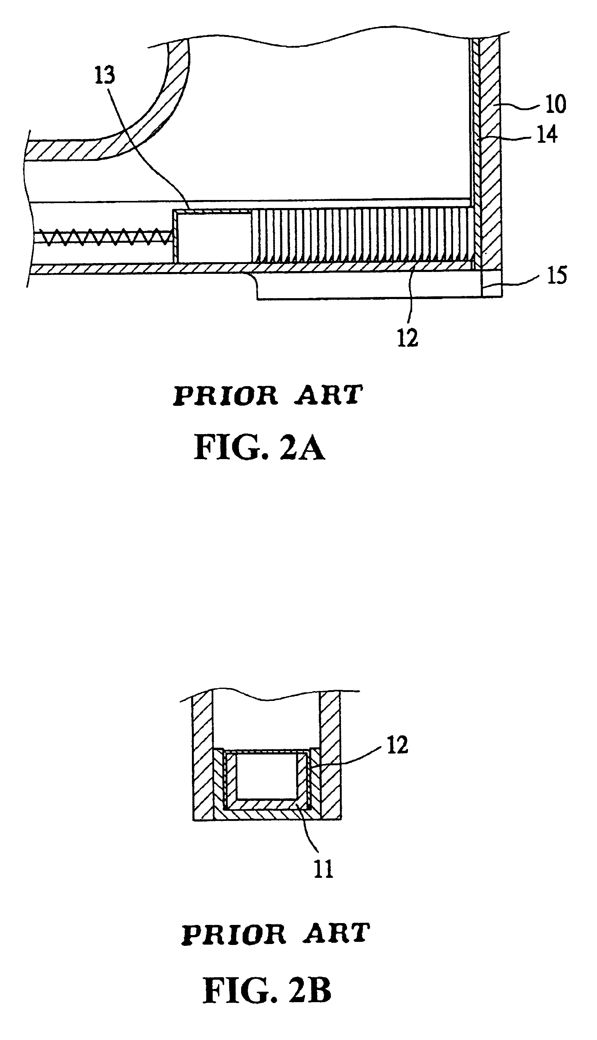
Referring to FIG. 5, the wire-pressing element is made as one unit from a plastic material and is denoted as reference number 50. The center of the wire-pressing element 50 is provided with a wire-pressing section 51 (the wire-pressing section is of any shape, and the shape of the wire-pressing section in the present invention is a rectangular shape). The bottom face of the wire-pressing section 51 is an arch-shaped slot 52 having an opening facing downward. The shape of the slot can be semi-hemisphere or other shape. In the present invention, a semi-hemisphere is employed. The slot 52 is used for the pressing of the wire and the two sides of the wire-pressing section 51 are respectively formed into corresponding nailing holes 53. The nailing holes 53 at the front lateral edge of the wire-pressing element 50 corresponding to the front side edge of the stapling device body 10 is appropriately corresponding to the staple impaction plate 14 (as shown in FIG. 6A) such that the staple ro...


PUM


Abstract

A detachable insulation wire-pressing element of a stapling device is disclosed. The wire-pressing element has a wire-pressing section at the center of the element and the bottom face of the wire-pressing section is provided with a wire slot having an opening facing downward the two sides of the wire-pressing section are respectively provided with a corresponding nailing hole, and the nailing hole is corresponding to a staple-impacting plate of the stapling device, thereby a wire-pressing element is formed. When the front edge of the wire-pressing element is aligned with the front edge of the stapling device the nailing holes are corresponding to the staple-impacting plate of the stapling device, and thereby a staple row utilized in the stapling device and by aligning the wire-pressing element with the front edge of the stapling device, the wire-pressing element can be used to secure insulation wires. The wire-pressing element can be utilized in stapling device for outdoors and indoors.< / PTEXT>

Description

(a) Field of the InventionThe present invention relates to a detachable insulation wire-pressing element of a stapling device, and in particular, to a wire-pressing element having a wire-pressing section and nailing holes allowing a stapling device to secure wires or the like at indoors or outdoors.(b) Description of the Prior ArtAs shown in FIGS. 1 and 2, there is shown a conventional stapling device for mounting wires of an article (electrical appliance) which utilizes a "II" shaped staple row 20. The stapling device has a body 10 having a "u" shaped slot seat 11. The two sides of the slot seat 11 are correspondingly formed with a staple slot 12 for the sliding of the "II" shaped staple row 20. The pushing seat 13 at the rear portion of the body 10 pushes forward the staple row 20, and the front end of the interior of the body 10 is provided with a staple-impacting plate 14 to force out a staple from the staple row 20. The bottom face of the body 10 has an arch-shaped wire slot se...

Claims


Application Information

Patent Timeline
Patent Type & Authority Patents(United States)
IPC IPC(8): B25C5/00B25C5/06
CPCB25C5/06B25C5/00
Inventor CHEN, TUNG-I
Owner CHEN TUNG I
Why Eureka
Try Eureka