Temperature regulation of fluid ejection printheads

a technology of fluid ejection and printhead, which is applied in the direction of printing, inking apparatus, other printing apparatus, etc., can solve the problems of power consumption, low power consumption, and inability to meet the requirements of application

Inactive Publication Date: 2003-10-21
SILVERBROOK RES PTY LTD +1
View PDF5 Cites 99 Cited by
  • Summary
  • Abstract
  • Description
  • Claims
  • Application Information

AI Technical Summary

Problems solved by technology

This is because the two main contenders--thermal ink jet and piezoelectric ink jet--each have severe fundamental problems meeting the requirements of the application.
The most significant problem with thermal ink jet is power consumption.
This is approximately 100 times that required for these applications, and stems from the energy-inefficient

Method used


Image

  • Temperature regulation of fluid ejection printheads
  • Temperature regulation of fluid ejection printheads
  • Temperature regulation of fluid ejection printheads

Examples


Embodiment Construction

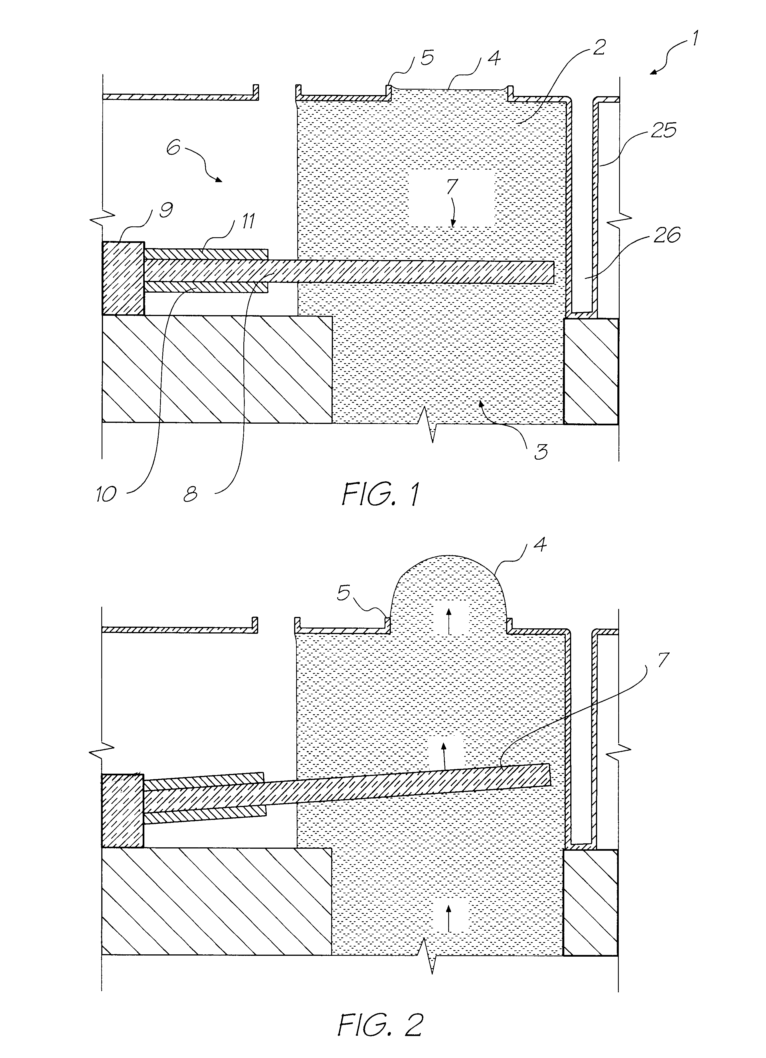
The preferred embodiment is a 1600 dpi modular monolithic print head sutable for incorporation into a wide variety of page width printers and in print-on-demand camera systems. The print head is fabricated by means of Micro-Electro-Mechanical-Systems (MEMS) technology, which refers to mechanical systems built on the micron scale, usually using technologies developed for integrated circuit fabrication.

As more than 50,000 nozzles are required for a 1600 dpi A4 photographic quality page width printer, integration of the drive electronics on the same chip as the print head is essential to achieve low cost. Integration allows the number of external connections to the print head to be reduced from around 50,000 to around 100. To provide the drive electronics, the preferred embodiment integrates CMOS logic and drive transistors on the same wafer as the MEMS nozzles. MEMS has several major advantages over other manufacturing techniques:

mechanical devices can be built with dimensions and acc...


PUM


Abstract

A method of operation of a fluid ejection printhead within a predetermined thermal range so as to print an image, wherein the printhead temperature is measured and below a predetermined threshold, the printhead is heated to a desired temperature before printing. Where thermal bend actuators are used in the printhead, heating is controlled so as to be insufficient to cause ejection of fluid.

Description

The present invention relates to the operation of fluid ejection printheads such as inkjet printers or the like and, in particular, discloses a method of providing for thermal compensation for variations in required ejection energies.Many different types of printing have been invented a large number of which are presently in use. The known forms of printers have a variety of methods for marking the print media with a relevant marking media. Commonly used forms of printing include offset printing, laser printing and copying devices. Dot matrix type impact printers, thermal paper printers, film recorders, thermal wax printers, dye sublimation printers and inkjet printers both of the drop on demand and continuous flow type. Each type of printer has its own advantages and problems when considering cost, speed, quality, reliability, simplicity of construction and operation etc.In recent years, the field of inkjet printing, wherein each individual pixel of ink is derived from one or more ...

Claims


Application Information

Patent Timeline
IPC IPC(8): B41J2/14B41J2/05B41J2/16B41J2/04
CPCB41J2/04528B41J2/04543B41J2/04553B41J2/04563B41J2/04573B41J2/04585B41J2/04588B41J2/04591B41J2/04596B41J2/04598B41J2/14427B41J2/1623B41J2/1626B41J2/1628B41J2/1631B41J2/1632B41J2/1635B41J2/1639B41J2/1642B41J2/1646B41J2/1648B41J2/175B41J2/17513B41J2/17553B41J2/04541B41J2202/21B41J2002/14491
Inventor SILVERBROOK, KIA
Owner SILVERBROOK RES PTY LTD
Why Eureka
Try Eureka