Optical interferometer

an interferometer and optical technology, applied in the field of optical interferometers, can solve problems such as difficult stable measurements

Inactive Publication Date: 2003-10-21
YOKOGAWA ELECTRIC CORP
View PDF9 Cites 13 Cited by
  • Summary
  • Abstract
  • Description
  • Claims
  • Application Information

AI Technical Summary

Benefits of technology

Further, the light beam reflected on an emitting surface of the beam splitter does not pass through the same optical path in the beam splitter. Accordingly, the interference in the beam splitter can be avoided and stable measurements can be conducted.
Further, the light beam reflected on an emitting surface of the beam splitter does not pass through the same optical path in the beam splitter. Accordingly, the interference in the beam splitter can be avoided and the stable measurements can be conducted.

Problems solved by technology

As described above, in the conventional optical interferometer, the beam splitter 4 is perpendicularly arranged to the incident optical axis, however, the light beams reflected by the incident surface and the emitting surface of the beam splitter 4 are interfered with each other, or return to the fiber 1, thereby, stable measurements are difficult.

Method used


Image

  • Optical interferometer
  • Optical interferometer
  • Optical interferometer

Examples


first embodiment

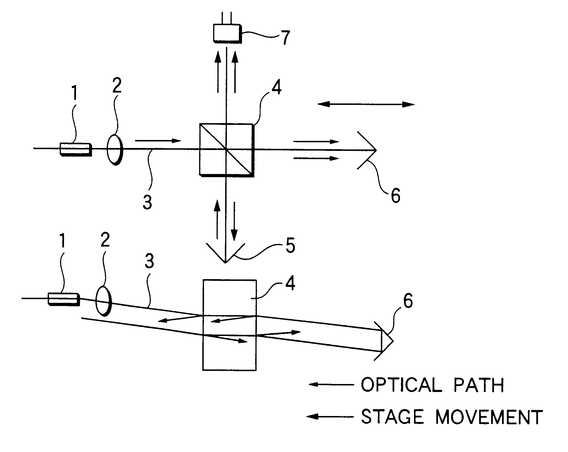
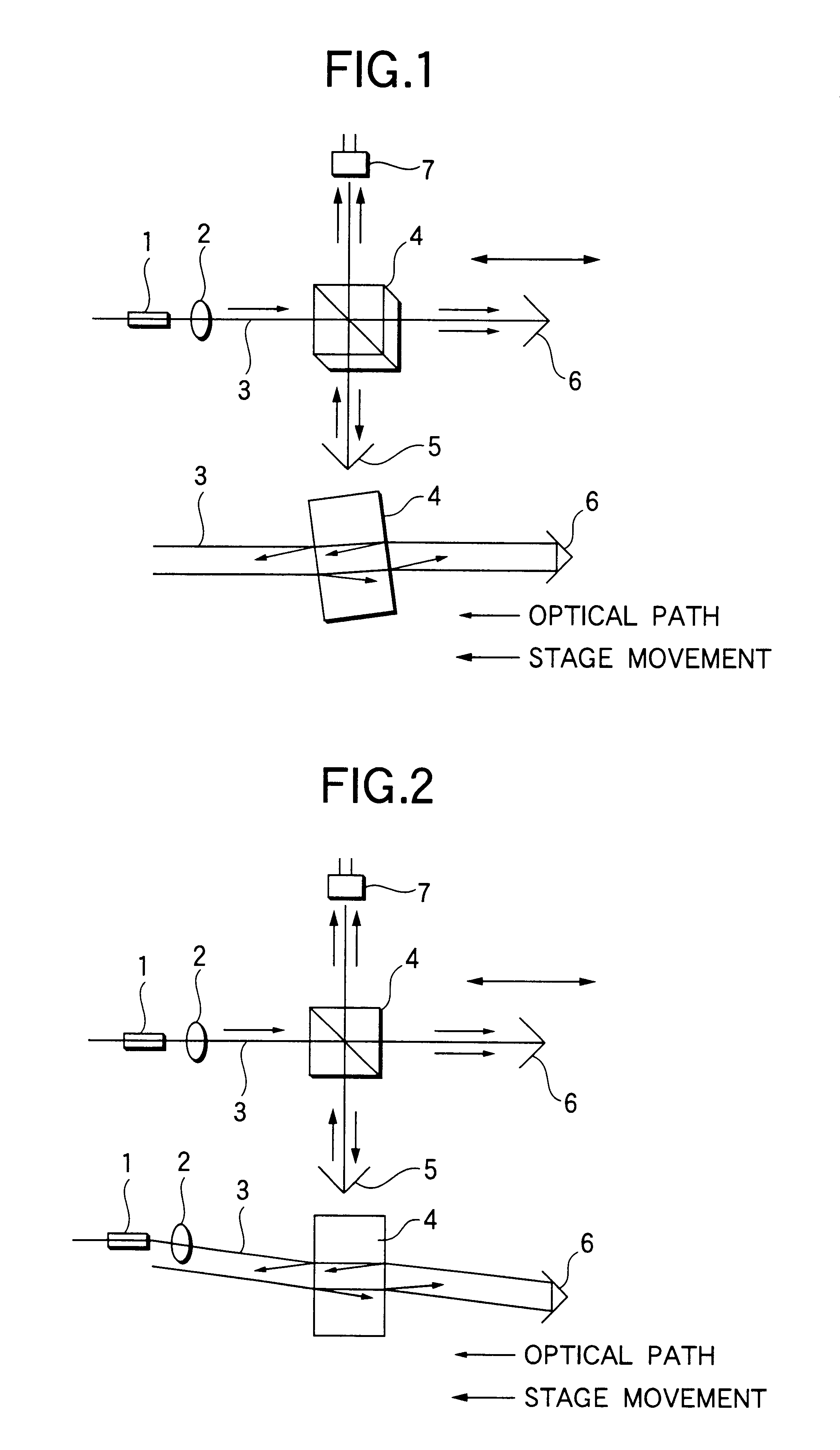
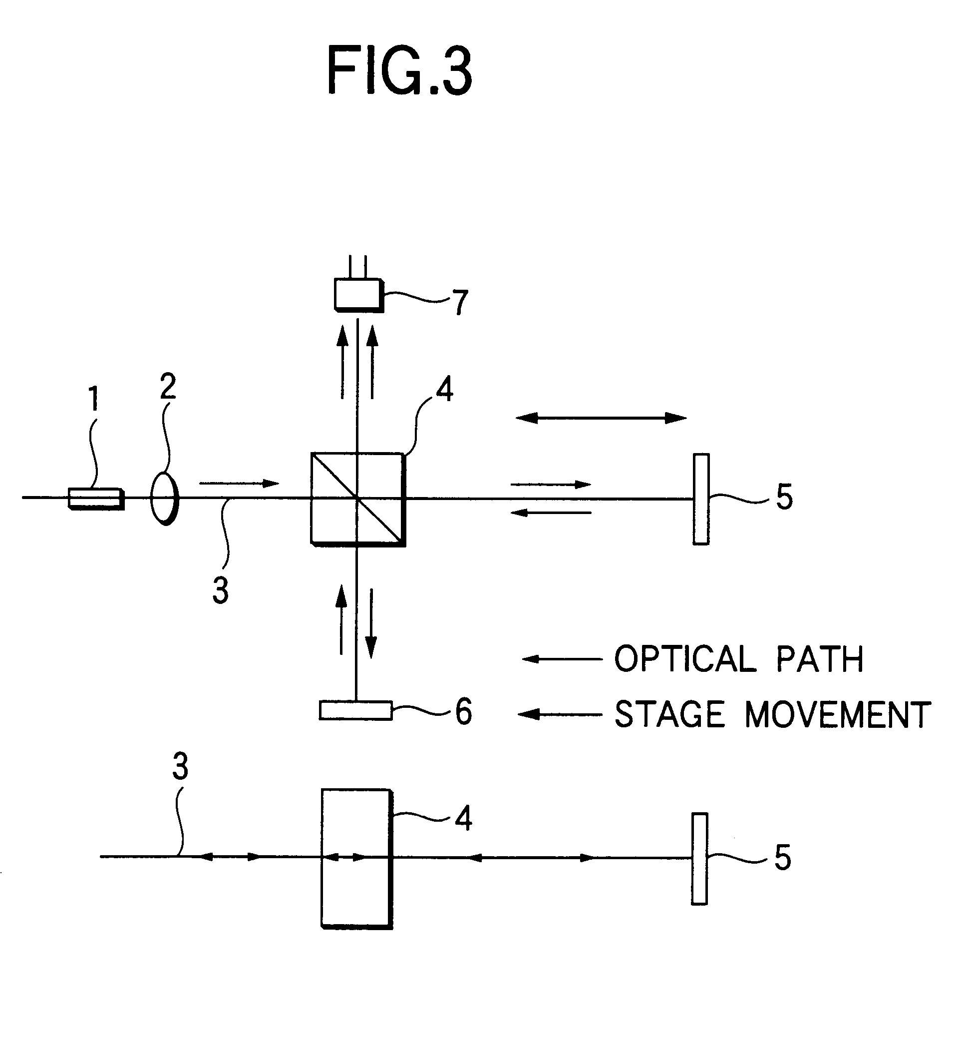
Initially, FIG. 1 is a view showing an outline structure of an optical interferometer according to a first embodiment of the present invention. As well as the conventional optical interferometer (refer to FIG. 3), in FIG. 1, numeral 1 is an optical fiber for outputting a light beam to be measured, numeral 2 is a lens for converting the light beam from the optical fiber into a parallel light beam as an incident light beam 3, numeral 4 is a beam splitter for branching the light beam to two optical paths perpendicular to each other to make a reflected light beam and a transmitted light beam, numeral 5 is a first reflection unit for reflecting the reflected light beam to return the reflected light beam to the beam splitter, numeral 6 is a second reflection unit for reflecting the transmitted light beam to return the transmitted light beam to the beam splitter, and numeral 7 is a light receiver for receiving the wave-combined light beam from the beam splitter 4.

The reflected light beam r...

second embodiment

FIG. 2 is a view showing an outline structure of an optical interferometer according to a second embodiment of the present invention. As well as the conventional optical interferometer (refer to FIG. 3), in FIG. 2, numeral 1 is an optical fiber, numeral 2 is a lens, numeral 3 is an incident light beam, numeral 4 is a beam splitter, numerals 5 and 6 are reflectors (the first and the second reflection units), and numeral 7 is a light receiver. The elements 1-7 has the same structure as those of the first embodiment of the invention.

According to the second embodiment, central axes of the optical fiber 1 and the central axis of the lens 2 are shifted from each other. Accordingly, the incident light beam 3 which is made a parallel light beam by the lens 2, is incident not perpendicularly to the beam splitter 4, but with an angle with respect to the normal line of a incident surface of the beam splitter 4. Therefore, the same effect as in the first embodiment can be obtained.

In this conne...


PUM


Abstract

The optical interferometer in which the incident light beam 3 is branched into 2 optical paths of the reflection light and the transmission light which cross at right angle with each other by the beam splitter 4, and on each optical path, the reflection light is totally reflected by the first reflection unit 5, and the transmission light is totally reflected by the second reflection unit 6, and the reflection lights by both reflection units 5 and 6 are wave-combined again by the beam splitter 4, and received by the light receiver 7. The beam splitter 4 by which the incident light beam is wave-separated and wave-combined, is arranged with a little inclination from the vertical to the incident light beam.

Description

1. Field of the InventionThe present invention relates to an optical interferometer which is used, for example, in the field of the optical instrumentation engineering.2. Description of the Related ArtFIG. 3 is a view showing an outline structural example of a conventional optical interferometer. In FIG. 3, numeral 1 is an optical fiber, numeral 2 is a lens, numeral 3 is an incident light beam, numeral 4 is a beam splitter, numerals 5 and 6 are reflection units, and numeral 7 is a light receiver.The optical interferometer converts, as shown in FIG. 3, the incident light beam 3 from the optical fiber 1 into a parallel light beam by the lens 2, and branches the parallel light beam to two optical paths of a transmission light beam and a reflection light beam which are perpendicular to each other, by the beam splitter 4, and the reflection light beams by the reflection units 5 and 6 placed in the respective optical paths at a right angle, are wave-combined again by the beam splitter 4.A...

Claims


Application Information

Patent Timeline
Patent Type & Authority Patents(United States)
IPC IPC(8): G01B9/02G01D5/26
CPCG01B9/02059G01D5/266
Inventor AKIKUNI, FUMIO
Owner YOKOGAWA ELECTRIC CORP
Why Eureka
Try Eureka