
High power variable slide RF tuner

a variable slide, rf tuner technology, applied in the direction of mechanically variable capacitor details, variable capacitors, capacitors, etc., can solve the problems of inability to design high-power rf amplifiers using the newest high-power transistors, inability to handle the power level of variable rf tuning capacitors, and inability to handle the power level of the required level

Inactive Publication Date: 2003-10-21
RAYTHEON CO
View PDF1 Cites 19 Cited by
  • Summary
  • Abstract
  • Description
  • Claims
  • Application Information

AI Technical Summary

Problems solved by technology

However, the power handling capability of other lumped element components that comprise a high power transistor amplifier (e.g. capacitors, resistors, inductors, etc.) has not increased nearly as rapidly.
Therefore, the design of high power RF amplifiers using the newest high power transistors is difficult due to the lack of high power lumped element components.
In particular, variable RF tuning capacitors that can handle the required power levels are not available.
However, if the power output is pushed just a small percentage beyond this, the capacitors will fail.
Higher power variable capacitors are available, but they are not suitable at RF frequencies (they self resonate below 900 MHz).

Method used


Image

  • High power variable slide RF tuner
  • High power variable slide RF tuner
  • High power variable slide RF tuner

Examples


Embodiment Construction

Illustrative embodiments and exemplary applications will now be described with reference to the accompanying drawings to disclose the advantageous teachings of the present invention.

While the present invention is described herein with reference to illustrative embodiments for particular applications, it should be understood that the invention is not limited thereto. Those having ordinary skill in the art and access to the teachings provided herein will recognize additional modifications, applications, and embodiments within the scope thereof and additional fields in which the present invention would be of significant utility.

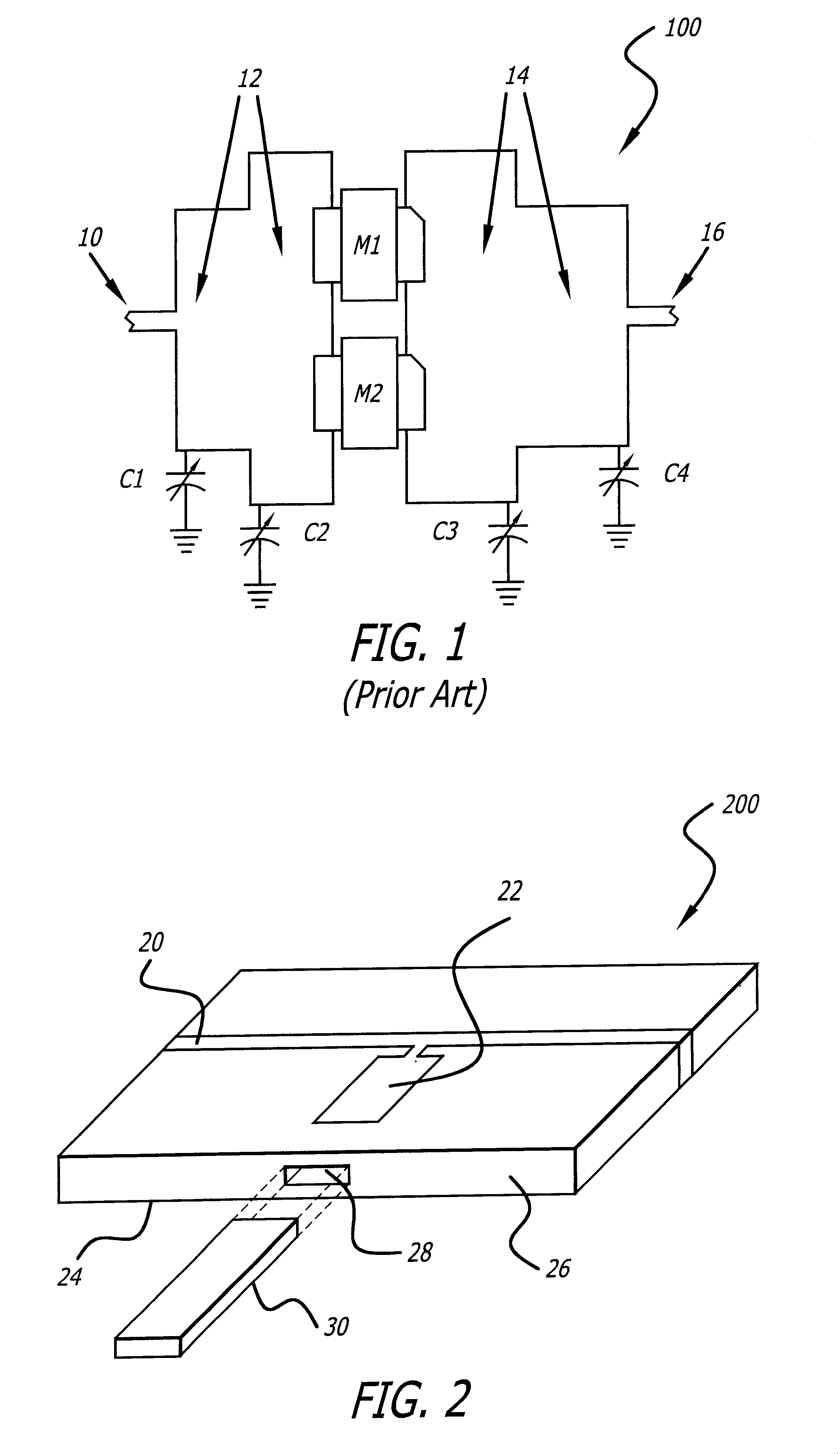
FIG. 1 is a diagram of a typical embodiment of a conventional high power RF microstrip amplifier 100. A 50 ohm input transmission line 10 transitions into transmission lines 12 of much lower impedances (the wider transmission lines). At the transition between different width lines, a shunt capacitor (C1, C2) to ground is placed. The low impedance line 12 is then...


PUM


Abstract

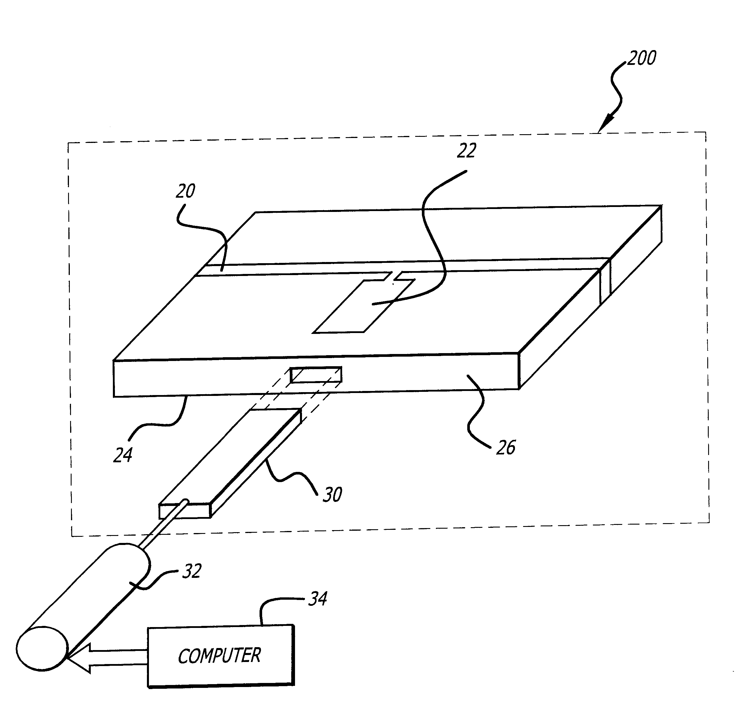
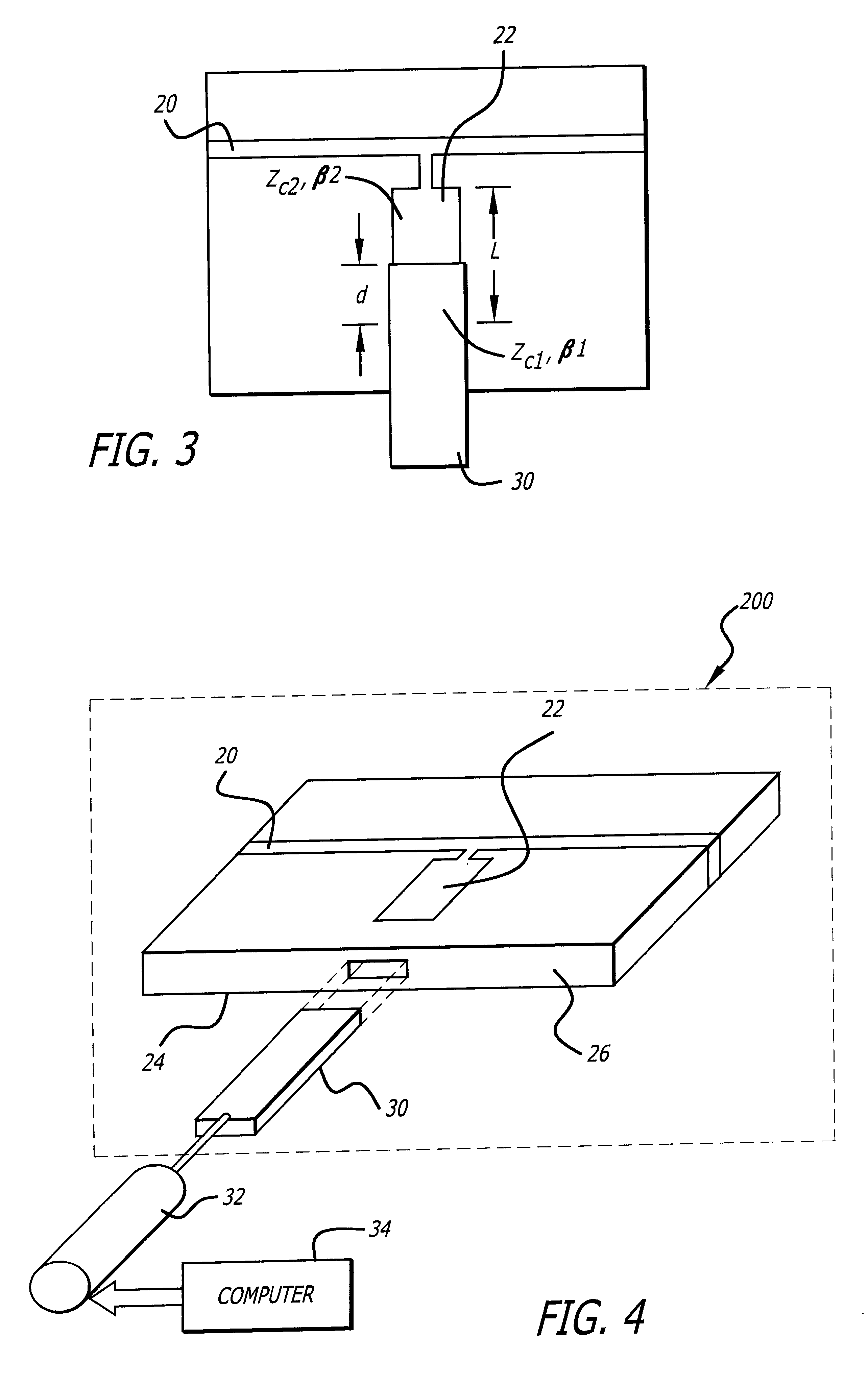
A high power slide tuning capacitor (200) integrated into a circuit board adapted to function at RF and microwave frequencies. The capacitor (200) includes a dielectric substrate (26) with a cavity (28) cut into a side of the substrate (26); a ground plane (24) mounted on a bottom surface of the dielectric substrate (26); a microstrip patch (22) mounted on a top surface of the dielectric substrate (26) and positioned above the cavity (28); and a movable dielectric stub (30) which engages the cavity (28) such that a variable length of the stub (30) is positioned beneath the microstrip patch (22). The microstrip patch (22) can be coupled to a desired circuit trace (20), effectively forming a shunt capacitor to ground.

Description

1. Field of the InventionThe present invention relates to electronic circuits and systems. More specifically, the present invention relates to variable capacitors for use in high power radio frequency applications.2. Description of the Related ArtHigh power radio frequency (RF) transistors are ever increasing in power. In the last several years, the power of RF transistors in the cell phone band has doubled approximately every two years. Amplifier circuits often use several of these transistors together to generate thousands or even millions of watts of power. However, the power handling capability of other lumped element components that comprise a high power transistor amplifier (e.g. capacitors, resistors, inductors, etc.) has not increased nearly as rapidly. Therefore, the design of high power RF amplifiers using the newest high power transistors is difficult due to the lack of high power lumped element components. In particular, variable RF tuning capacitors that can handle the ...

Claims


Application Information

Patent Timeline
Patent Type & Authority Patents(United States)
IPC IPC(8): H05K1/16H01P5/04H01G5/013H03F3/60
CPCH01G5/0138H05K1/162H05K1/0272H05K2201/10196H05K2201/0187H05K2201/0715
Inventor OBERT, THOMAS L.BROWN, KENNETH W.DRAKE, THOMAS A.
Owner RAYTHEON CO
Learn More