Heat sink subassembly

a technology of heat sinks and sub-assemblies, applied in the field of computer systems, can solve problems such as system malfunction or error, electronic devices may generate heat, and electrical devices may be affected by the condition of the sub-assembly,

Inactive Publication Date: 2003-10-28
GLOBALFOUNDRIES US INC
View PDF6 Cites 130 Cited by
  • Summary
  • Abstract
  • Description
  • Claims
  • Application Information

AI Technical Summary

Problems solved by technology

However, when operating, each electronic device may generate heat.
If enough heat is generated within the enclosure to cause any of the enclosed electronic devices to operate outside of their operational temperature range, problems may occur.
For example, in some cases, increased temperature may cause a system to malfunction or behave erroneously.
Sometimes, increased heat may even damage the electronic devices or components within the enclosure.
In other systems though, factors such as the size of the enclosure or the orientation of the device within the enclosure may limit the beneficial effects of convection.
One problem that arises in systems that simply radiate heat is that the heat may accumulate inside an area in the enclosure.
For example, convection may no longer assist in cooling if all of the air in an area becomes equally heated.
The top component may quickly lose any benefits of convection due to the accumulation of heated air in the top of the enclosure.
Another situation where this might arise occurs when many devices are mounted in close proximity in an enclosure.
Each

Method used


Image

  • Heat sink subassembly
  • Heat sink subassembly
  • Heat sink subassembly

Examples


Embodiment Construction

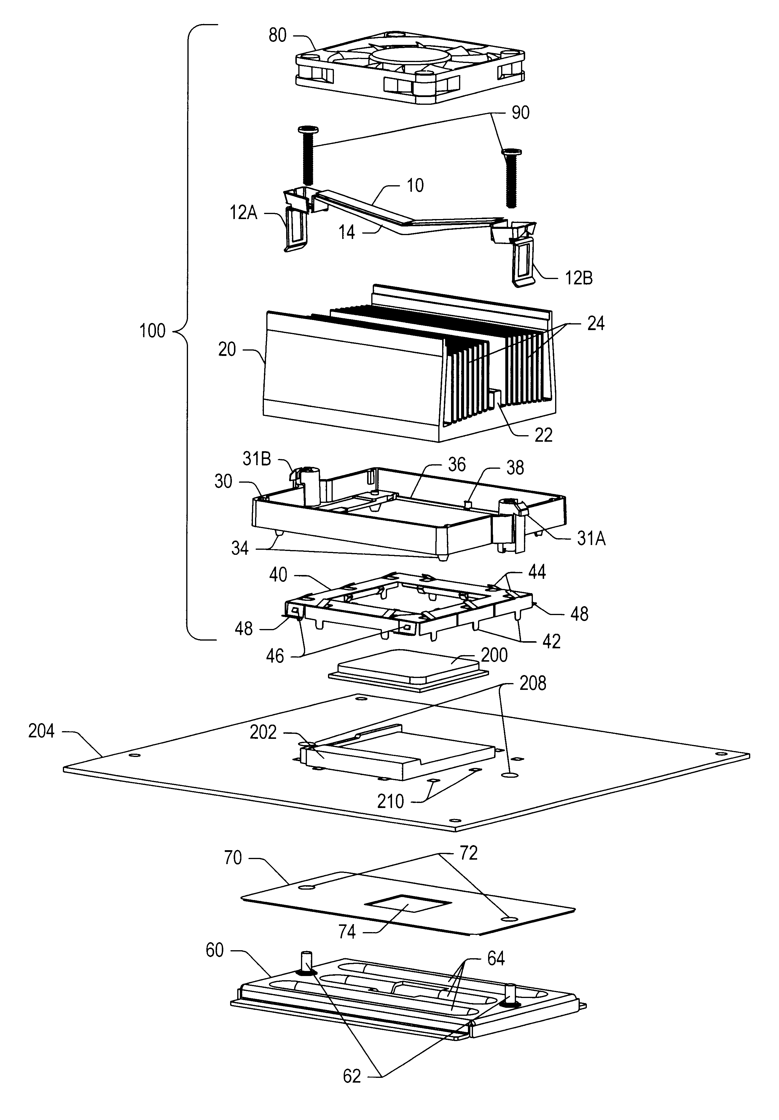
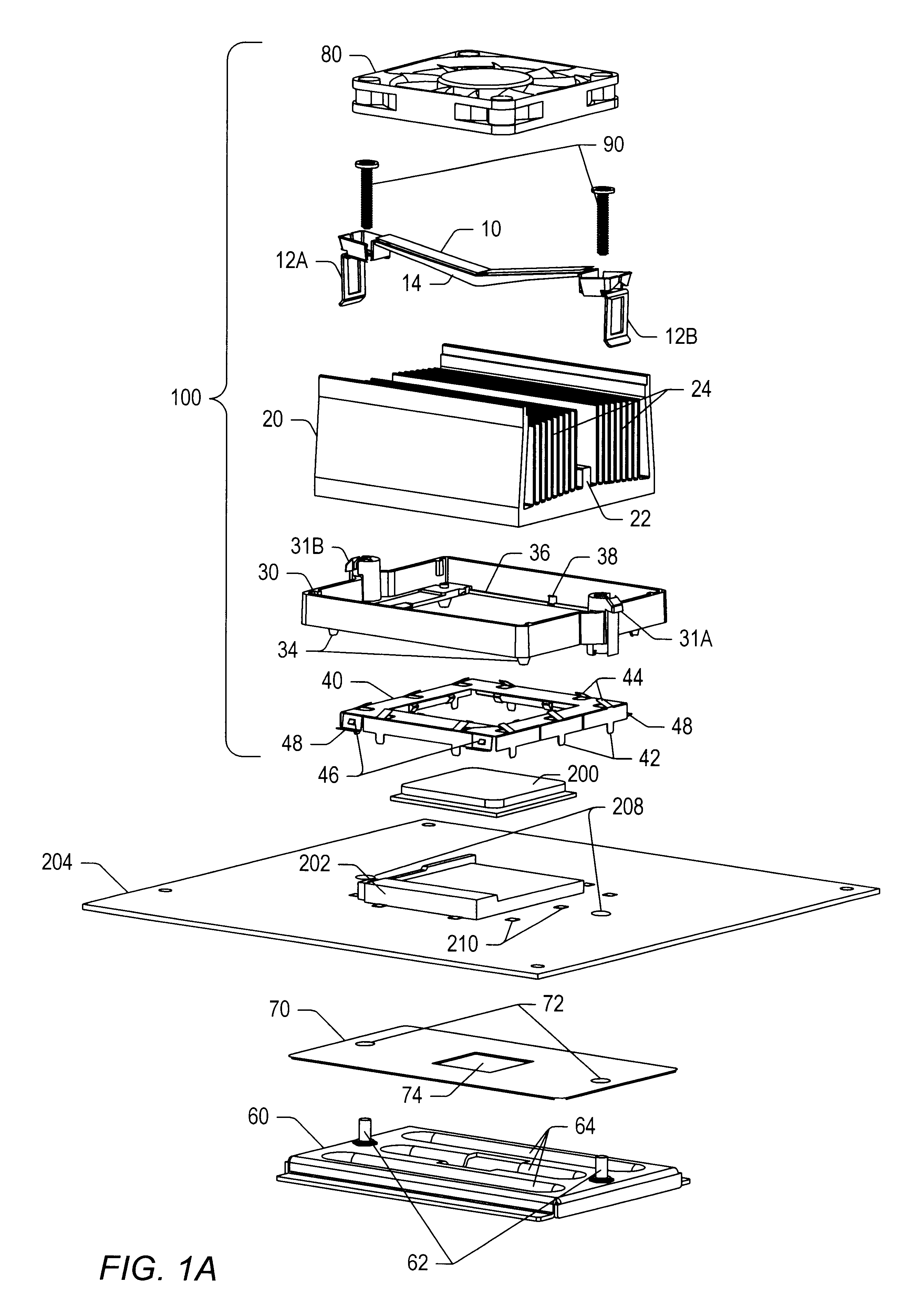
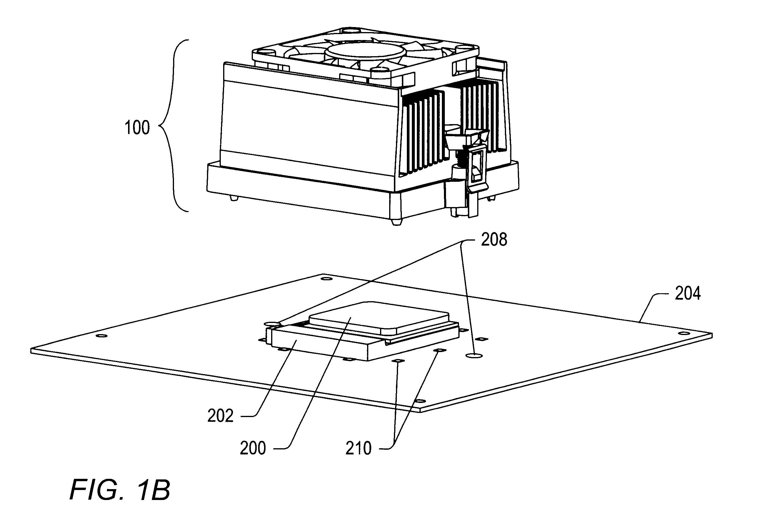
FIG. 1A shows an exploded perspective view of one embodiment of a computer system that includes a heat sink subassembly 100, an integrated circuit 200, a printed circuit board 204, an insulator 70, and a stiffening plate 60. As shown, heat sink subassembly may include a fan 80, a spring clip 10, two screws 90, a heat sink 20, a retainer 30, and electromagnetic shielding 40. In alternative embodiments, several of the components (e.g., screws 90, fan 80, and / or electromagnetic shielding 40) shown in FIG. 1A may not be included in a subassembly sold by a heat sink manufacturer. Note that as described herein, individual components labeled by the same reference number followed by a distinct alphabetic identifier (e.g., tangs 12A and 12B) may be collectively referred to by that number alone (e.g., tangs 12). Also, note that when descriptions refer to a directional orientation of a component (e.g., above or below another component, or having an upper or lower surface), the directional orie...


PUM


Abstract

A heat sink subassembly may include a retainer comprising several attachment points, a heat sink coupled to the retainer, and a force-generating device. The heat sink includes several fins, one of which is shorter than the other fins. The force-generating device is coupled to at least one of the attachment points and to the first fin. The force-generating device is configured to exert a force that keeps the heat sink securely coupled to the retainer when the force-generating device is coupled to the attachment points.

Description

1. Field of the InventionThis invention relates to computer systems and, more particularly, to heat sinks used to dissipate heat in computer systems.2. Description of the Related ArtElectronic enclosures may contain many different electronic devices that are designed to operate within certain temperature ranges. However, when operating, each electronic device may generate heat. If enough heat is generated within the enclosure to cause any of the enclosed electronic devices to operate outside of their operational temperature range, problems may occur. For example, in some cases, increased temperature may cause a system to malfunction or behave erroneously. Sometimes, increased heat may even damage the electronic devices or components within the enclosure.In order to reduce heat-related problems, many electronic enclosures include cooling devices. One simple example of a cooling device is a passive heat sink that radiates heat from a device into the surrounding air. A passive heat sin...

Claims


Application Information

Patent Timeline
IPC IPC(8): H01L23/40H01L23/34
CPCH01L23/4006H01L2023/4062H01L2023/4081H01L2023/4087H01L2924/0002H01L2924/00
Inventor EYMAN, LEWIS MICHAELPAULSEL, ROGER Q.SHARP, STANLEY O.DELSO, JAMES W.
Owner GLOBALFOUNDRIES US INC
Why Eureka
Try Eureka