Spherical locking device

a technology of locking device and spherical body, which is applied in the direction of couplings, machine supports, manufacturing tools, etc., can solve the problem of not being versatile enough to easily hold objects

Inactive Publication Date: 2003-11-04
RONSHEIM STEPHEN E
View PDF5 Cites 38 Cited by
  • Summary
  • Abstract
  • Description
  • Claims
  • Application Information

AI Technical Summary

Problems solved by technology

But in many instances, they are not versatile enough to easily hold an object in exactly the attitude or orientation which the user needs or desires.

Method used


Image

  • Spherical locking device
  • Spherical locking device
  • Spherical locking device

Examples


Embodiment Construction

For the purposes of promoting an understanding of the principles of the invention, reference will now be made to the embodiment illustrated in the drawings and specific language will be used to describe the same. It will nevertheless be understood that no limitation of the scope of the invention is thereby intended, such alterations and further modifications in the illustrated device, and such further applications of the principles of the invention as illustrated therein being contemplated as would normally occur to one skilled in the art to which the invention relates are intended to be protected.

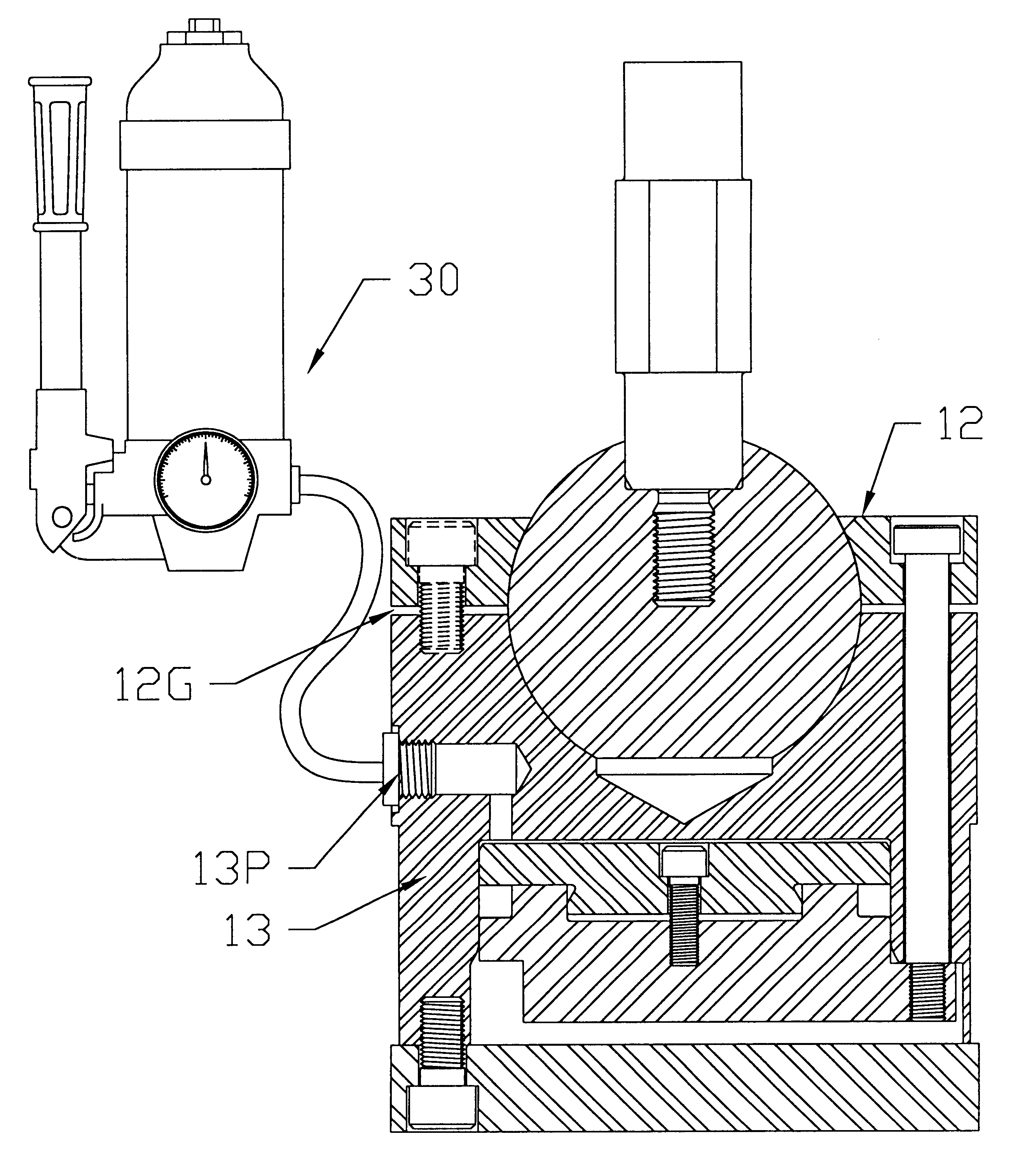
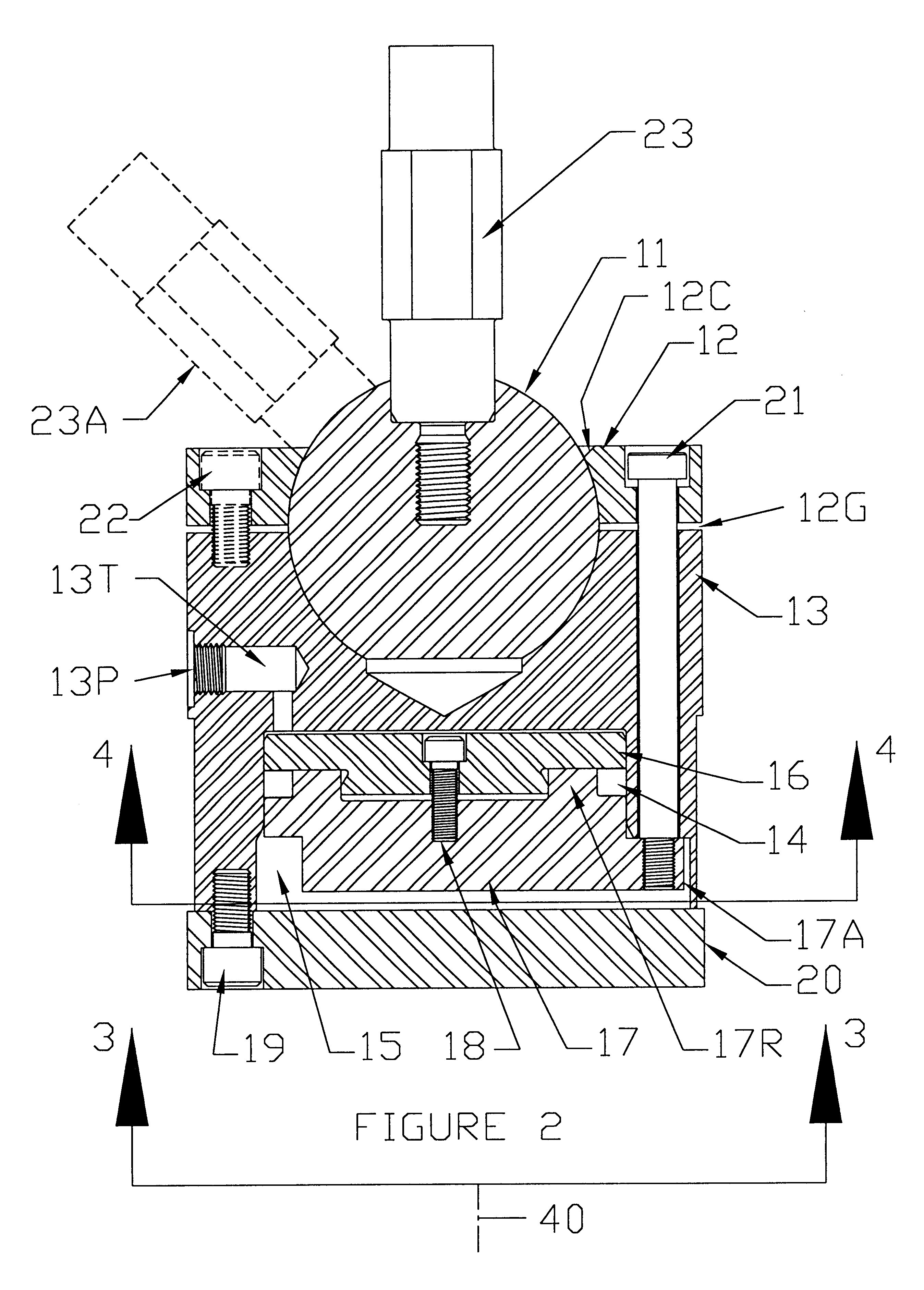
Referring now to the drawings in detail, the illustrated embodiment includes a ball 11 received in a two-part socket including an upper socket portion in a clamping plate 12, and a lower socket portion in a body 13. The body has a generally cylindrical downwardly-opening cavity 15 extending downward to the bottom edge of the body. A generally-cylindrical piston assembly is received in the ...


PUM


Abstract

A cylindrical body has a first part-spherical socket portion in the top, fittingly receiving a ball. A ball retainer has a second part-spherical socket portion facing the first part-spherical socket portion and receiving the ball therein. A post has a proximal end fixed to the ball and extends radially outward from the ball and away from the body to a distal end, and has screw threads at the distal end to receive a fastener thereon for attachment of an object to the distal end of the post. The ball-in-socket mounting of the post enables freely swiveling the ball and thereby the swiveling the distal end of the post to an infinite number of loci in a spherical envelope centered at the center of the ball, as well as enabling the post, and any object mounted to the post, to be rotated on a radial line from the center of the ball to the location of mounting of the object to the post. The body has a hydraulic cylinder in the bottom receiving a piston. The piston is connected to the ball retainer for clamping the retainer on the ball and thereby locking the ball in the socket portions, to lock the post and thereby the object mounted to the post, in a position and orientation in space as selected by the user. A hydraulic pump assembly is coupled to the body to apply and release pressure on the piston.

Description

1. Field of the InventionThis invention relates generally to holding devices for objects, and more particularly to a device for holding a workpiece or other object, or for holding another workpiece holding device in any of a variety of positions and orientations for as long as desired.2. Description of the Prior ArtIn many industries, professions, and crafts, it is essential to hold an object stationary in some selected position and orientation in space for viewing it, for viewing with it, or working on it, or somehow dealing with it. Clamps and vises are probably the most common holding devices for such purposes. But in many instances, they are not versatile enough to easily hold an object in exactly the attitude or orientation which the user needs or desires. The present invention is addressed to this problem.Described briefly, according to a typical embodiment of the present invention an object holding device includes a body having a first part-spherical socket portion fittingly ...

Claims


Application Information

Patent Timeline
Patent Type & Authority Patents(United States)
IPC IPC(8): F16C11/10F16M11/14F16C11/04F16M11/02
CPCF16C11/106F16M11/14F16M2200/022Y10T403/259Y10T403/32631Y10T403/25Y10T403/32311Y10T403/22
Inventor RONSHEIM, STEPHEN E.
Owner RONSHEIM STEPHEN E
Why Eureka
Try Eureka