Angled coaxial electrical connector device

a technology of electrical connectors and coaxial cables, which is applied in the direction of coupling device connections, two-pole connections, electrical apparatus, etc., can solve the problems of large number of parts and require a relatively large number of operations, and achieve the effect of convenient operation

Inactive Publication Date: 2003-11-04
RAYDIALL
View PDF3 Cites 11 Cited by
  • Summary
  • Abstract
  • Description
  • Claims
  • Application Information

AI Technical Summary

Benefits of technology

There thus exists a need for an angled coaxial connector device that is free to turn about an axis and that is easy to make.
The device of the invention is thus simple and economic to make.
It is thus possible to manufacture a single type of connection device suitable for occupying different angular orientations, and suitable for replacing different types of connector, thereby reducing costs, in particular by improved stock management.
In an embodiment of the invention, the portion in relief is suitable for snap-fastening in the housing, thus making the support element and the connector element particularly simple and quick to assemble together.
The support element may include a locking element that is movable between first and second positions, the first position allowing the connector element to be mounted in the support element and the second position preventing the connector element from being withdrawn from the support element while allowing the connector element to turn freely.

Problems solved by technology

That known connector has a large number of parts and requires a relatively large number of operations to be performed when assembling the parts.

Method used


Image

  • Angled coaxial electrical connector device
  • Angled coaxial electrical connector device
  • Angled coaxial electrical connector device

Examples


Embodiment Construction

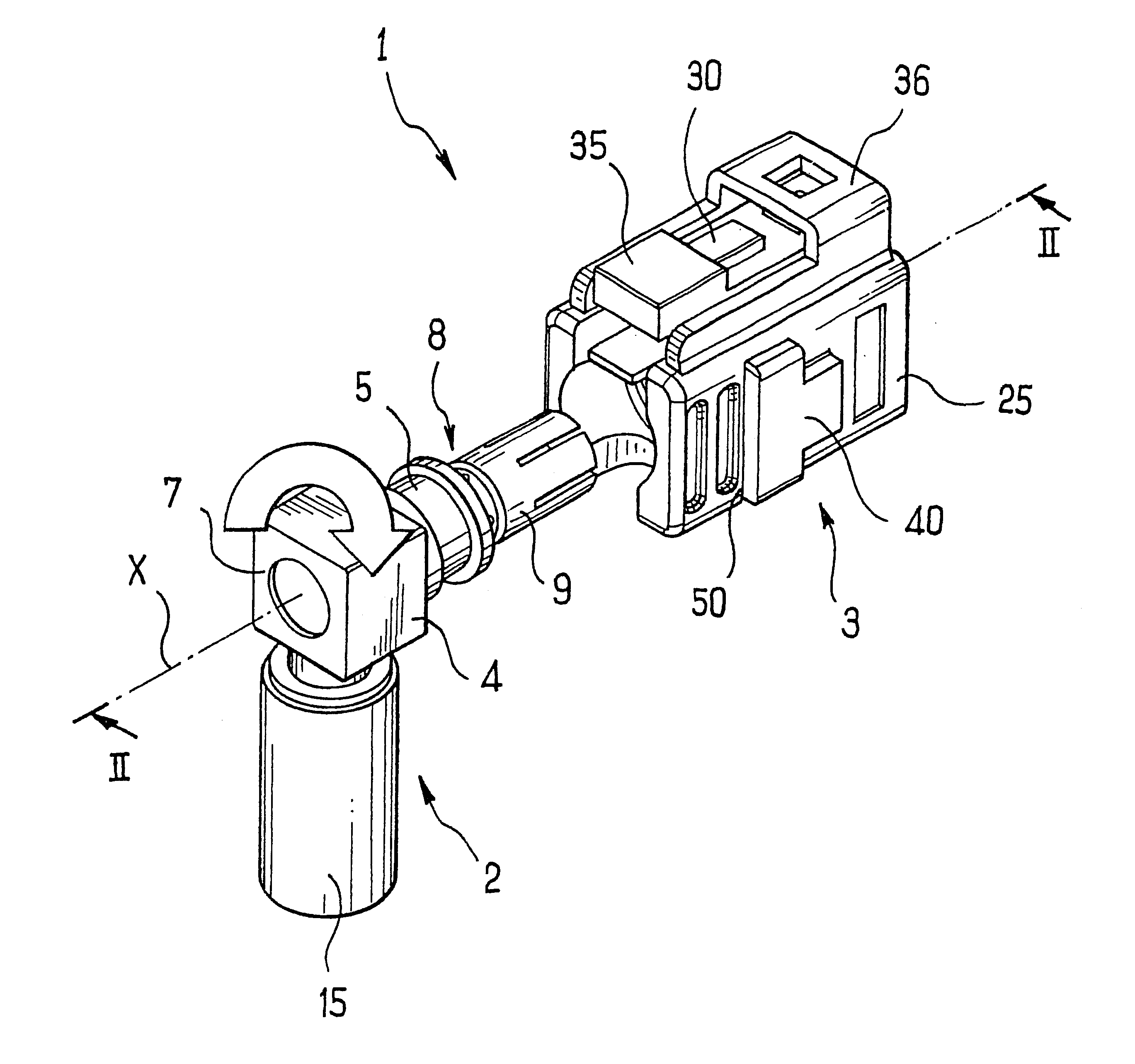
FIG. 1 shows a coaxial electrical connector device 1 in accordance with the invention, comprising a coaxial connector element 2 and a support element 3.

The device 1 serves to connect a coaxial cable (not shown) to a socket base (not shown) fixed to a panel.

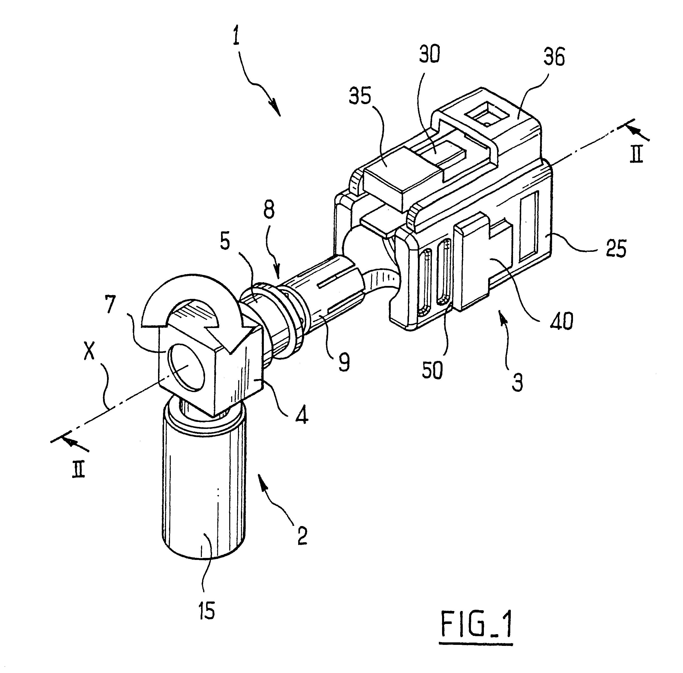
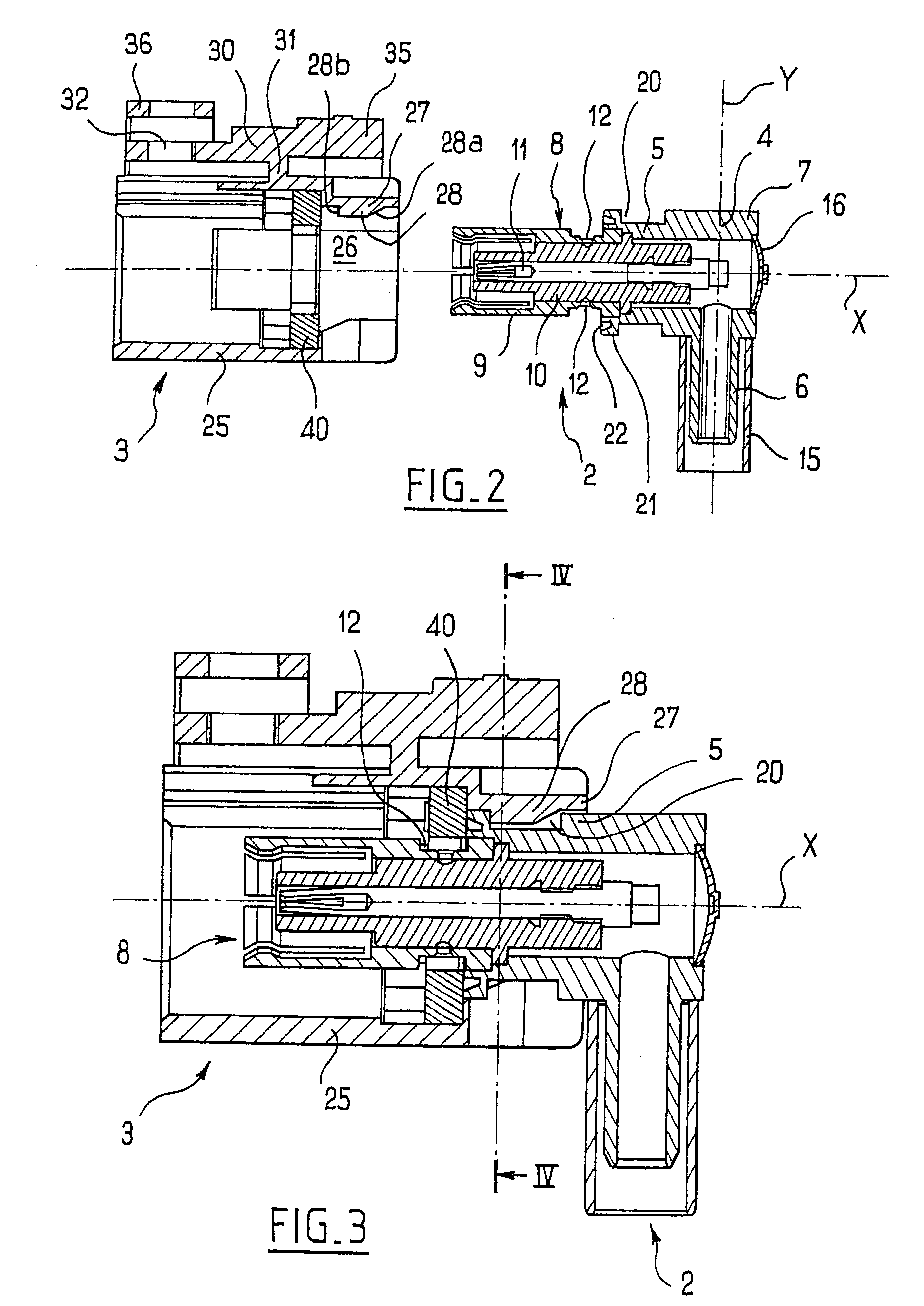
The connector element 2 comprises a body 4 having a right-angle bend, defining first and second tubular portions 5 and 6 which are circularly cylindrical about respective perpendicular axes X and Y. These portions 5 and 6 are connected together by means of a bend 7 whose outside shape is generally that of a rectangular block. The bend 7 has a rear opening closed by a stopper 16.

The first tubular portion 5 receives a coaxial contact element 8 constituted by an outer conductor 9, insulation 10, and a central conductor 11, the insulation 10 being held in the outer conductor 9 by local deformation of the wall of said outer conductor 9 in the bottom of a groove 12 therein.

The second tubular portion 6 is designed to receive a coaxial ca...


PUM


Abstract

The present invention provides an angled coaxial electrical connector device, comprising a box suitable for being fixed on a base and a coaxial connector element suitable for being assembled with said box and comprising first and second generally tubular portions having respective perpendicular axes, the first portion having a coaxial contact element and the second portion being suitable for receiving a coaxial cable, the box presenting an internal cavity suitable for receiving at least part of said first tubular portion, and wherein one of the elements taken from the connector element and the box includes a housing formed by an annular groove, and the other element includes at least one portion in relief, each such portion in relief presenting an elastically deformable tab suitable for snap-fastening in said annular groove, said tab being suitable for sliding in said annular groove when the connector element and the box are assembled together so that the connector element is free to turn relative to the box about an axis of rotation associated with the box.

Description

The present invention relates to an angled coaxial electrical connector device, serving in particular to enable a coaxial cable to be connected to a base.U.S. Pat. No. 5, 277, 590 discloses an electrical connector enabling a coaxial cable to be connected to a connector element which is fixed to a panel, for example. The connector comprises an outer body receiving two subassemblies that are free to turn about two respective axes of rotation that are perpendicular. Those subassemblies are put into place in the outer body so as to be free to turn by means of rings. That known connector has a large number of parts and requires a relatively large number of operations to be performed when assembling the parts.OBJECTS AND SUMMARY OF THE INVENTIONThere thus exists a need for an angled coaxial connector device that is free to turn about an axis and that is easy to make.The invention achieves this by a novel angled coaxial electrical connector device comprising a support element suitable for ...

Claims


Application Information

Patent Timeline
Patent Type & Authority Patents(United States)
IPC IPC(8): H01R13/00H01R13/646
CPCH01R9/0518H01R2103/00
Inventor BAFFERT, JEAN-MARC
Owner RAYDIALL
Why Eureka
Try Eureka