Beverage filter cartridge

a beverage filter and cartridge technology, applied in the field of known disposable single-serving beverage filter cartridges, can solve the problems of aborting the brewing process, the side wall of the container buckles, and the failure of the outlet prob

Inactive Publication Date: 2003-11-11
KEURIG GREEN MOUNTAIN INC
View PDF9 Cites 371 Cited by
  • Summary
  • Abstract
  • Description
  • Claims
  • Application Information

AI Technical Summary

Benefits of technology

Companion objectives include a beneficial increase in beverage medium storage capacity, improvements in the manner in which the filter component is sealed to and radially supported by the container side wall, as well as improvements in the manner in which the lower end of the filter is positioned and anchored to the cartridge bottom.
In accordance with the present invention, the container side wall is provided with circumferentially spaced flutes which are strategically positioned to enhance resistance to buckling without interfering with or compromising the integrity of the seal between the side wall and the filter component. The location at which the filter component is joined to the interior side wall of the container is lowered to achieve a beneficial increase in beverage medium storage capacity. This location is defined by a tapered circular ledge against which the tapered filter component is reliably sealed.
The channels formed between the circumferentially spaced flutes serve to efficiently direct the brewed beverage downwardly towards the pierced container bottom, with an accompanying beneficial increase in turbulence in the head space defined between the filter element and container side wall.
In a third embodiment of the present invention, the circumferentially spaced flutes protrude sufficiently inwardly into the container interior to radially contact the filter element at circumferentially spaced locations. This radial contact beneficially guides the filter element into its centrally located position during assembly of the cartridge components, and, during the processing cycle, provides radial support which resists distortion and possible bursting of the filter element.

Problems solved by technology

One such problem stems from a tendency of the container side wall to buckle under the force exerted by the outlet probe as it pierces the container bottom.
This sometimes results in a failure of the outlet probe to achieve bottom penetration, thus aborting the brewing process because the brewed beverage cannot be delivered to the underlying cup.
Buckling of the container side wall also can distort the punctured orifice in the container bottom, thus compromising sealing and resulting in leakage of the brewed beverage.
Problems have also been encountered in reliably sealing the rim of the filter component to the interior side wall of the container, as well as in centrally securing the bottom of the filter component to the container bottom.
Failure to achieve a proper rim seal can cause the unsealed portion of the filter to collapse under brew pressure, resulting in the brewed beverage being contaminated by beverage medium residue escaping from the collapsed filter.
By the same token, contamination of the brewed beverage also can occur if the filter bottom is not centrally secured, resulting in the filter being punctured by the outlet probe as it projects upwardly through the container bottom.
Contamination of the brewed beverage also occurs occasionally when a filter element bursts under the pressure exerted by the heated liquid being infused with the beverage medium.
Still another problem stems from heat sealing the upper rim of the filter at or closely adjacent to the upper rim of the container side wall.
This increases the unoccupied so called "head space" between the outside of the filter and the surrounding container wall, and also limits the maximum amount of beverage medium that can be stored in the cartridge to that which can be contained within the filter.
In some cases, this can compromise the strength of the resulting brewed beverage.
Beverage strength can be optimized by filling the filter to its maximum capacity, but this can result in errant granules of the beverage medium spilling onto the container rim.
This in turn can disrupt the integrity of the seal between the cover and the container rim.

Method used


Image

  • Beverage filter cartridge
  • Beverage filter cartridge
  • Beverage filter cartridge

Examples


first embodiment

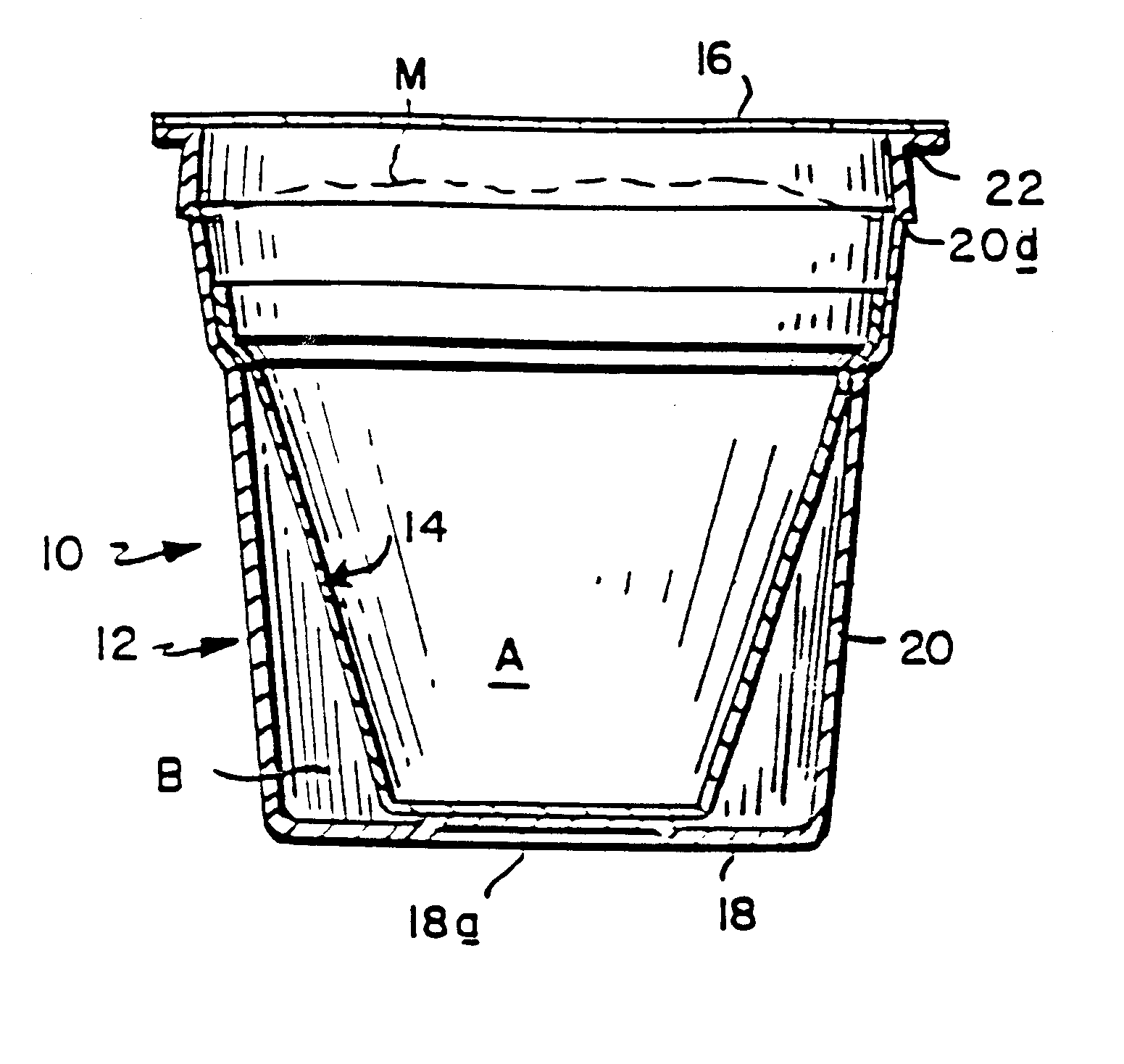
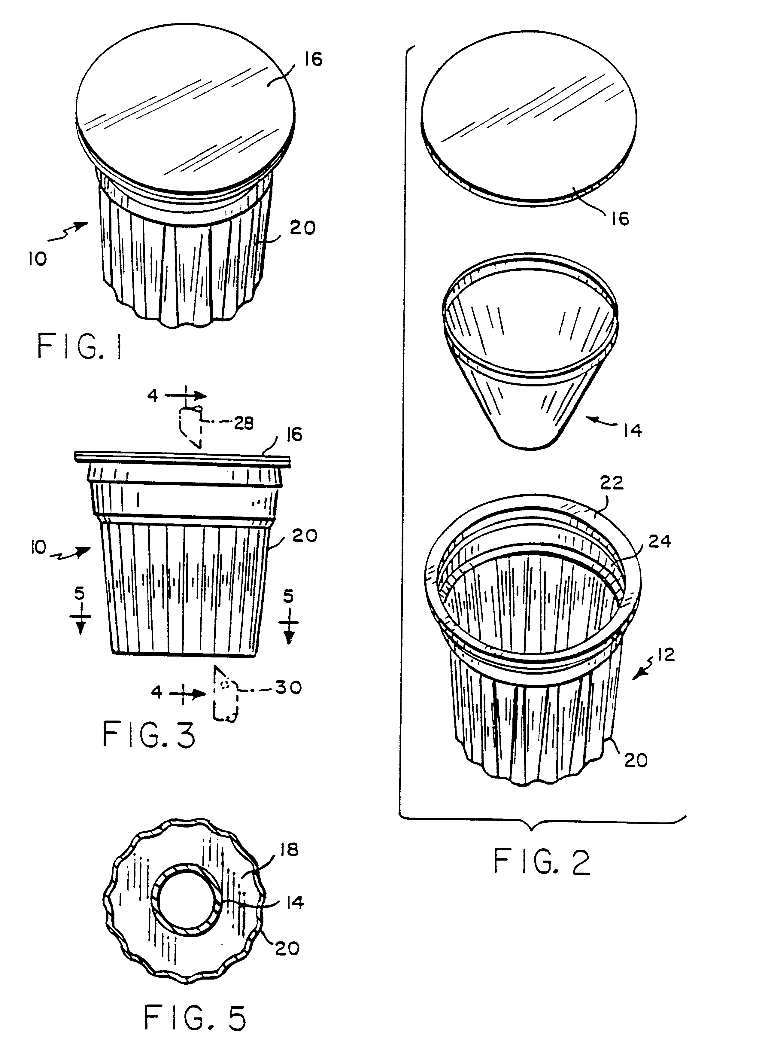
With reference initially to FIGS. 1-5, a beverage filter cartridge in accordance with the invention is generally depicted at 10. As shown in FIG. 2, the basic components of the beverage filter cartridge include an outer cup-shaped container 12, a generally cone-shaped filter element 14, and a planar circular lid 16.

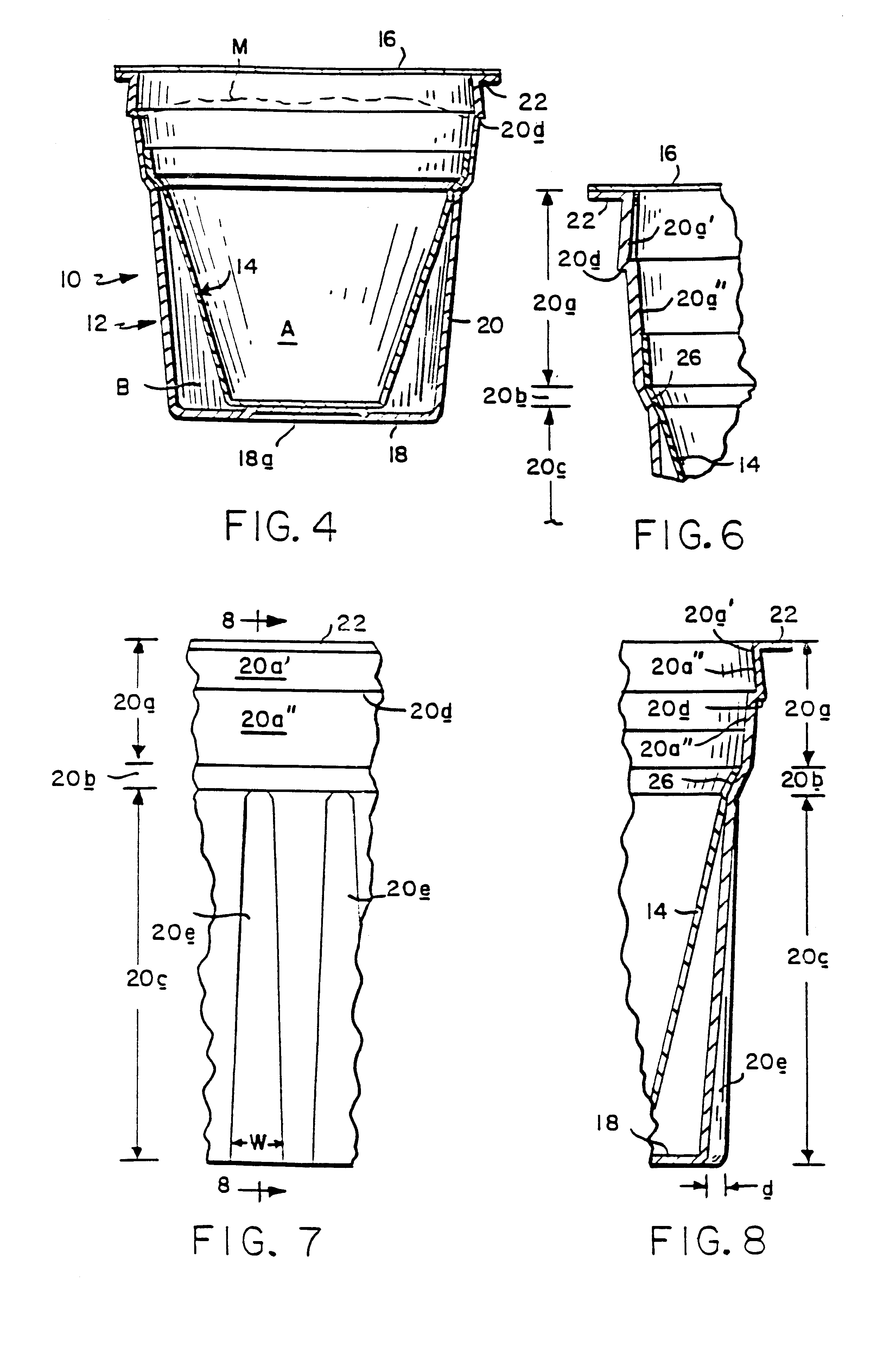
The cup-shaped container 12 has a bottom 18, and a side wall 20 extending upwardly from the bottom to a circular rim 22 surrounding an upper opening 24. With reference additionally to FIGS. 6-8, it will be seen that the side wall 20 has an upper section 20a extending downwardly from the rim 22 to an intermediate section defined by an inwardly tapered ledge 20b, and a lower tapered section 20c extending downwardly from ledge 20b to the bottom 18.

The upper wall section 20a is preferably subdivided into upper and lower segments 20a' and 20a". Moving down the cup, segment 20a' is flared outwardly, and segment 20a" tapers inwardly, with the juncture therebetween defining a sta...

second embodiment

In the second embodiment, the container bottom 218 is configured to provide a downwardly protruding centrally disposed reduced diameter boss 218a defining an interior sump 218b surrounded by an annular substantially planar bottom area. The bottom of the conical filter element is received in and secured to the bottom of the sump as at 218c.

The third embodiment illustrated in FIGS. 13-21 is also similar in many respects to the first embodiment. Again, similar features have been identified with similar reference numerals, but in a three hundred series.

The major difference between the first and third embodiments is that the latter has fewer and much deeper flutes 320e. As can be best seen in FIG. 19, the deeper flutes 320e contact and provide radial support for the filter element 314.

third embodiment

In light of the foregoing, it will now be appreciated by those skilled in the art that the present invention offers significant advantages over the known beverage filter cartridge described in the previously referenced patents. For example, the circumferentially spaced flutes 20e, 220e and 320e strengthen the container side wall against buckling when the bottom is pierced by the outlet probe 30. The deeper flutes 320e of the third embodiment offer the added advantage of radially supporting the filter element, which can be particularly beneficial during the processing cycle, when the filter element is being stressed by the infusion of pressurized heated liquid into the beverage medium.

In all embodiments, the downwardly diverging and gradually deepening of the flutes serves to promote downward flow of the brewed beverage in chamber B while beneficially encouraging turbulence. The upwardly protruding bosses 18a, 318a on the container bottoms of the first and third embodiments provide r...


PUM

PropertyMeasurementUnit
taper angleaaaaaaaaaa
impermeableaaaaaaaaaa
permeableaaaaaaaaaa

Abstract

A beverage filter cartridge includes a cup-shaped outer container with a bottom and a side wall extending upwardly from the bottom wall to a circular rim surrounding an upper opening. The side wall has an upper section extending downwardly from the rim to an intermediate section, and a tapered lower section configured to provide a plurality of circumferentially spaced flutes extending downwardly from the intermediate section to the bottom wall. A filter element subdivides the interior of the container into first and second chambers. A beverage medium is stored in the first chamber. A cover is joined to the side wall at the rim to close the upper opening. The cover is yieldably piercable to accommodate an injection of liquid into the first chamber for combination with the beverage medium to produce a beverage. The filter element is permeable to accommodate a flow of the beverage from the first chamber into the second chamber, and the bottom wall is yieldably piercable to accommodate an outflow of the beverage from the second chamber to the exterior of the cartridge.

Description

This invention relates to disposable single serve beverage filter cartridges.DESCRIPTION OF THE PRIOR ARTA known disposable single serve beverage filter cartridge is disclosed in U.S. Pat. Nos. 5,325,765 and 5,840,189 (Sylvan et al.), dated respectively Jul. 5, 1994 and Nov. 24, 1998, the disclosures of which are herein incorporated by reference.This beverage filter cartridge is comprised basically of an impermeable yieldably-piercable cup-shaped outer container internally subdivided by a permeable cone-shaped filter into first and second chambers. A granular or powdered dry beverage medium, e.g., roasted ground coffee, is stored in the first chamber, and the container is closed by an impermeable yieldably piercable lid.During a processing cycle, the lid and container bottom are pierced, respectively, by tubular inlet and outlet probes. The inlet probe admits heated liquid under pressure into the first chamber for infusion with the beverage medium, and the resulting brewed beverage ...

Claims


Application Information

Patent Timeline
Patent Type & Authority Patents(United States)
IPC IPC(8): B65D81/00A47J31/06B65D81/34B01D27/04B01D27/08B65D85/804
CPCB65D85/8043B65D85/8061A47J31/06
Inventor SWEENEY, RICHARDLAZARIS, NICHOLAS G.BEAULIEU, RODERICK H.BUCUZZO, WILLIAM P.
Owner KEURIG GREEN MOUNTAIN INC
Why Eureka
Try Eureka