Movement detector pad with resilient plate attachment

a technology of resilient plates and detector pads, applied in the field of moving detectors, can solve problems such as unresolved

Inactive Publication Date: 2003-11-25
LES DEV ANGELCARE
View PDF6 Cites 15 Cited by
  • Summary
  • Abstract
  • Description
  • Claims
  • Application Information

AI Technical Summary

Problems solved by technology

Therefore, the plates in these corner areas are fairly rigid and will shunt any force applied to these corner areas due to its rigidity thereby often not detecting movement over these corner areas.
These helical compression springs do not resolve the above-mentioned problem of stiffness in the corner areas of the plates shunting movement thereover.

Method used


Image

  • Movement detector pad with resilient plate attachment
  • Movement detector pad with resilient plate attachment
  • Movement detector pad with resilient plate attachment

Examples


Embodiment Construction

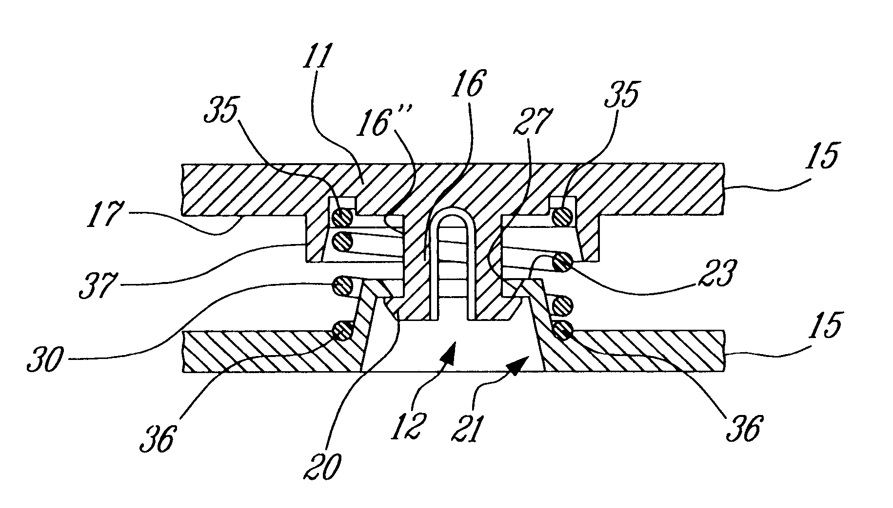
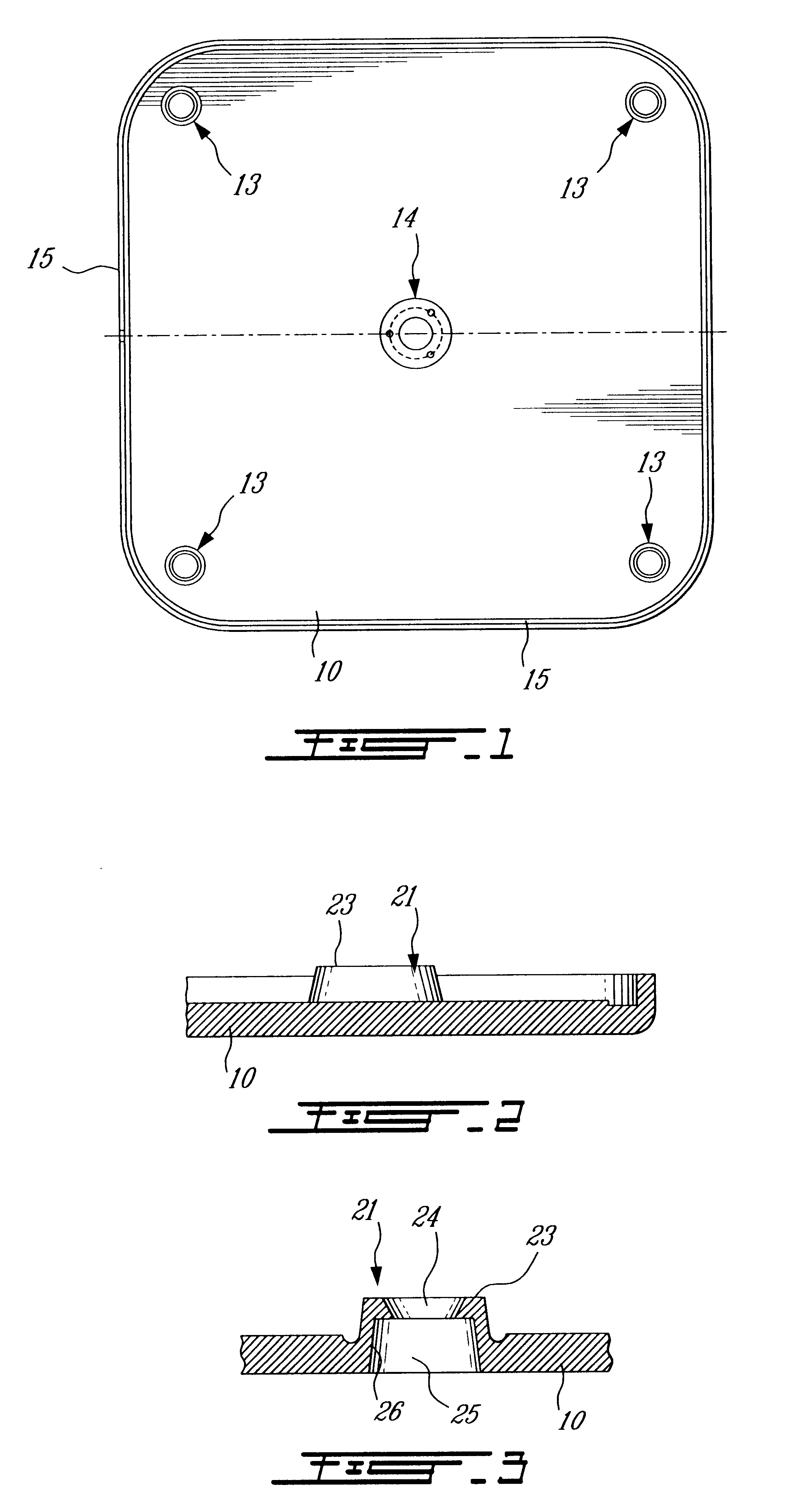
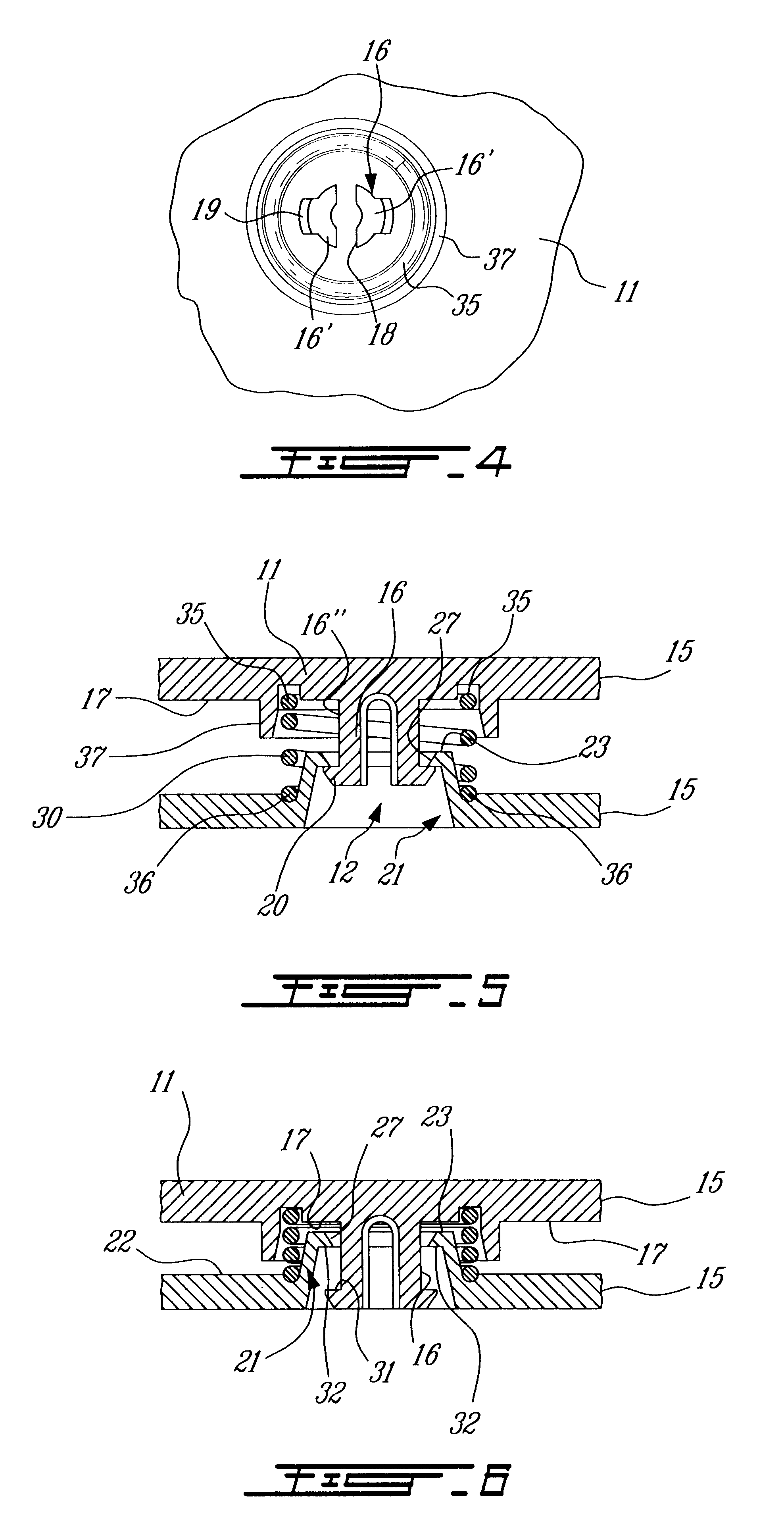
Referring to the drawings and more particularly to FIG. 1, there is shown the construction of the backing plate 10 of a movement detector pad constructed in accordance with the present invention. The collector plate 11 as shown only in fragmented section in FIGS. 5 and 6 is likely shaped in contour and is attached over the backing plate 10 by resilient attachment members 12 as illustrated in assembled form in FIGS. 5 and 6. These attachment members 12 are located in the corners of the plates at the locations 13 as illustrated in FIG. 1. A piezoelectric compression transducer (not shown) is secured in the area 14 as shown in FIG. 1. The collector plate 11 and backing plate 10 are molded of rigid plastic material and they are supported spaced apart in substantially parallel relationship by the resilient attachment members 12. These attachment members 12 are preferably disposed adjacent the outer circumferential edge 15 of these plates as illustrated in FIGS. 5 and 6. A piezoelectric t...


PUM


Abstract

Resilient attachment members interconnect a pair of flat plates of a movement detector pad and are preferably disposed in the corners of these flat plates. A piezoelectric transducer is disposed centrally between the plates to generate signals when the plates move with respect to one another. In one embodiment the resilient attachment members each have a connector pin which is connected to one of the plates and extends into a pin receiving hollow node formed in the other plates and projecting above an inner surface of the other plate. The end of the connector pin has lateral projections to engage within the node when both plates are spaced apart a predetermined distance by the pressure of helical springs which are disposed about each pin and its associated node. During movement of the pin within the node the pin is in substantially friction free movement whereby not to corrupt the movement signal generated by the piezoelectric crystal. These resilient attachment members interconnect the plates together while providing flexion thereof and which have the effect of maximizing the movement signal to the piezo by reducing the shunt effect that a more rigid corner plate connection has. The resilient members may also be constituted by leaf springs formed integral with one of the plates and connected to the other.

Description

The present invention relates to a movement detector pad which comprises a pair of plates between which a piezoelectric compression transducer is secured and more specifically to resilient attachment members which interconnect the plates together and provide attachment and resilient displacement of the plates with respect to one another.Reference is made to U.S. Pat. No. 6,146,332 which discloses a motion detector of the general type as described herein. In that patent the collector and backing plates are molded from plastic material and interconnected together by connector posts which are rigidly secured in the corner of the plates at distances which are remote from the piezoelectric compression transducer. Therefore, the plates in these corner areas are fairly rigid and will shunt any force applied to these corner areas due to its rigidity thereby often not detecting movement over these corner areas.In that patent it is also disclosed that to maintain the plates substantially in p...

Claims


Application Information

Patent Timeline
Patent Type & Authority Patents(United States)
IPC IPC(8): A61B5/11A61B5/113
CPCA61B5/113
Inventor PINSONNAULT, MAURICEMAUFFETTE, CLAUDEDREDGE, DAVID
Owner LES DEV ANGELCARE
Why Eureka
Try Eureka