
Four-way slide switch

a slide switch and four-way technology, applied in the direction of electric switches, basic electric elements, electric apparatus, etc., can solve the problems of high precision, increased switch cost, and high cost of contact spring discs, and achieve the difficulty of accurately and stably arranging contact spring discs at the center and at the positions in four directions

Inactive Publication Date: 2003-12-02
MIC ELECTRON CO
View PDF7 Cites 30 Cited by
  • Summary
  • Abstract
  • Description
  • Claims
  • Application Information

AI Technical Summary

Benefits of technology

According to the present invention, the contact spring disc, which raises problems in cost and in switch design, is used only for the center switch means, which is easily mounted and maintained. Strip-like contact spring pieces, which can be designed and fabricated easily and at low cost, are used for the four-ways switch means.
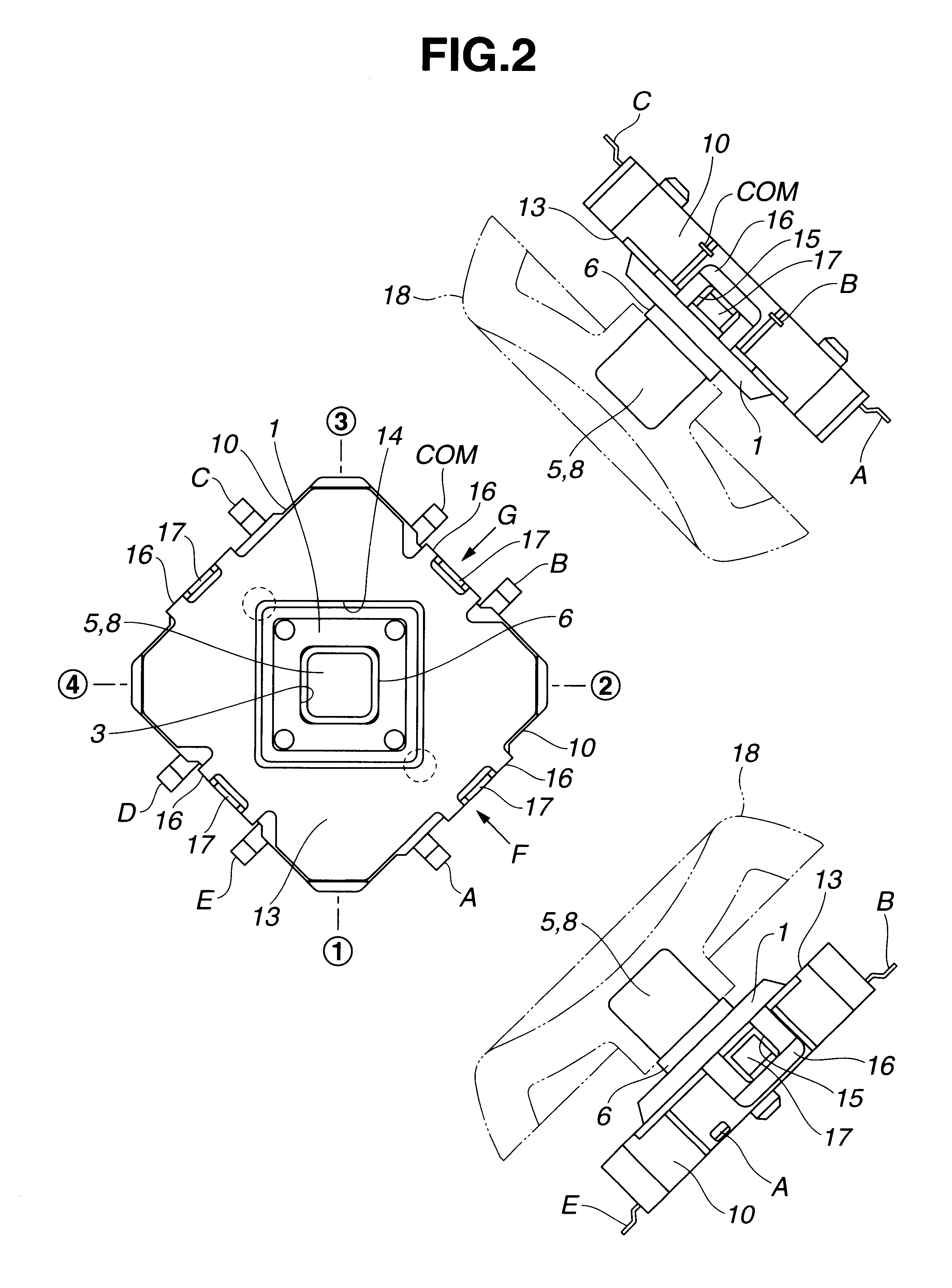
Moreover, the tiltable member, having contact spring units extended in four directions therefrom, and the control knob are disposed separately. The control knob is vertically engaged slidably into the square hole of the tiltable member. The protruded portions of the control knob are detachably engaged into the recessed portions of the tiltable member. When the center switch means is operated, only the control knob descends vertically and then restores. When the four-way switch means is operated, the tiltable member and the control knob operate in a linkage mode. This switch structure can eliminate an erroneous operation, thus effectively solving the problems in the prior art.

Problems solved by technology

However, minute diaphragm-type contact spring discs with high precision are required and are expensive.
Using five diaphragm-type contact spring discs leads to an increased cost of the switch.
Moreover, it is difficult to arrange the contact spring discs at the center and at positions in four directions accurately and stably.
The contact spring disc is easily displaced by external shock.
When the tilting member is erroneously depressed in a slant direction, the center switch means may not be turned on accurately.
Meanwhile, the switch means to be operated by only the oblique movement may be erroneously turned on.

Method used


Image

  • Four-way slide switch
  • Four-way slide switch
  • Four-way slide switch

Examples


Embodiment Construction

A four-way switch according to an embodiment of the present invention will be described below by referring to the attached drawings.

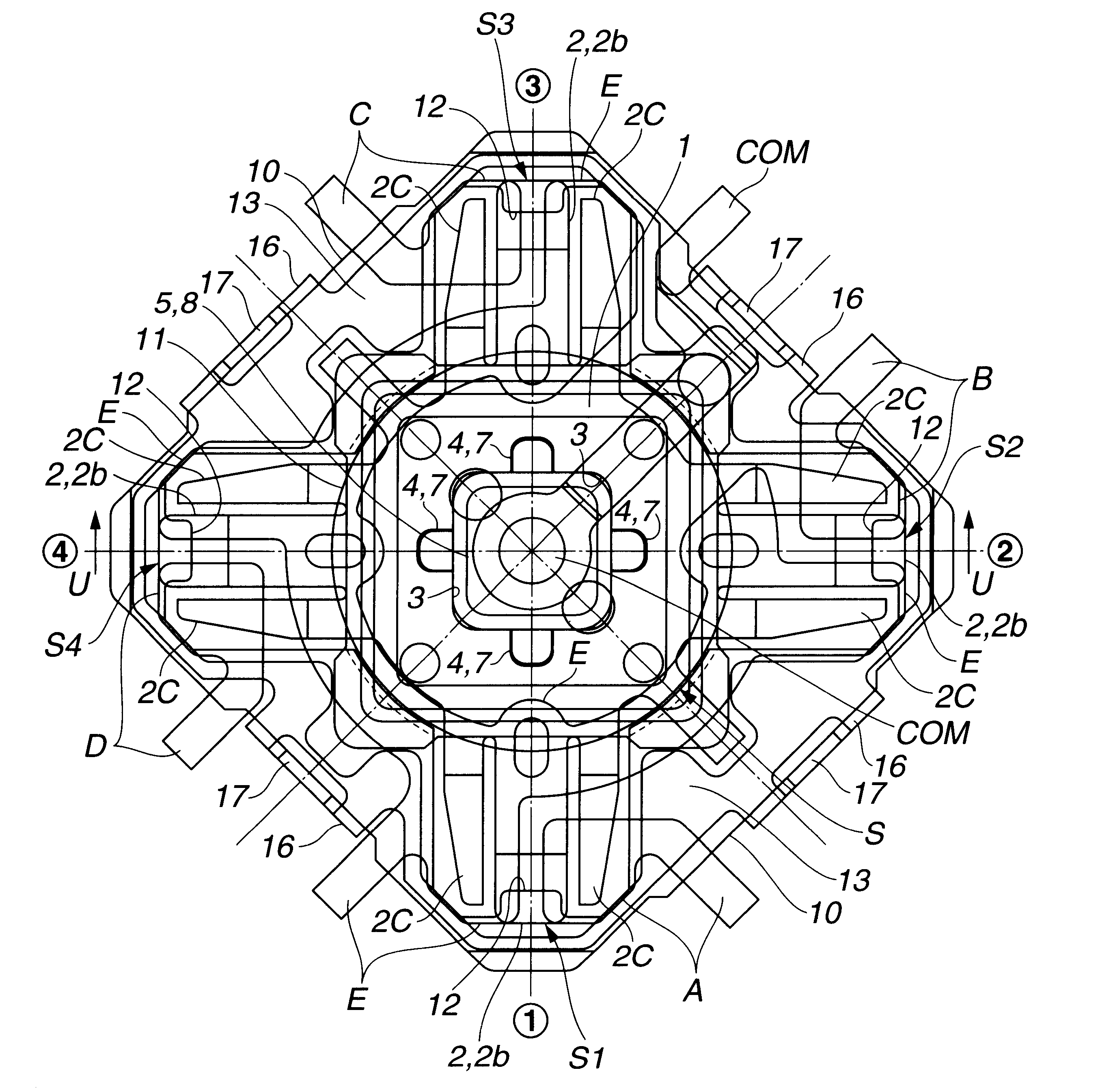
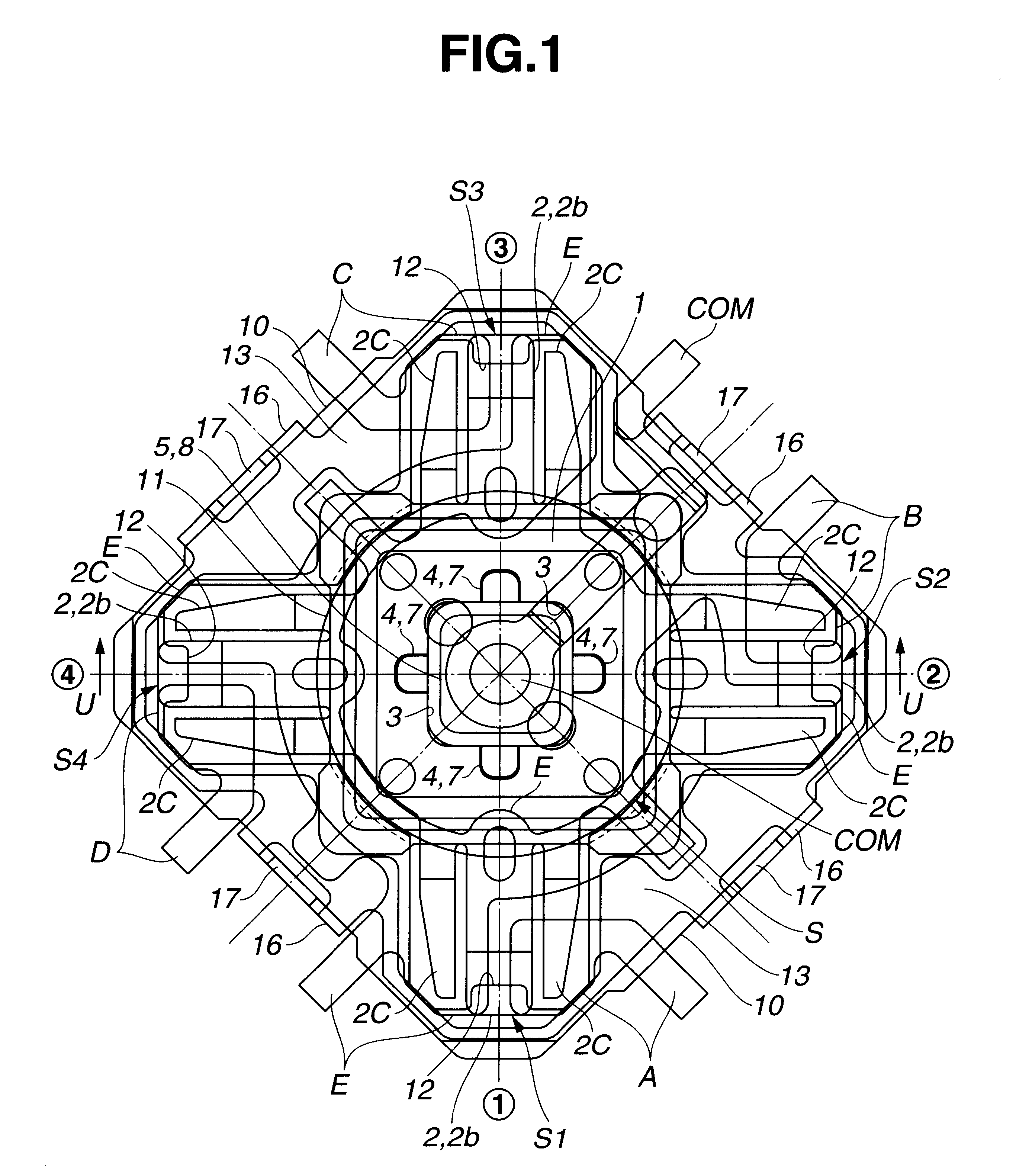
In the four-way switch, a tiltable member 1 includes an tiltable body la formed of an insulating square or circular plate and a contact resilient unit 2 formed of a conductive spring plate. The tiltable body la has a square opening 3 in the center thereof and has recessed portions at the lower ends of the inner surfaces of the square opening 3. The contact resilient unit 2 is formed of a base 2a of a conductive resilient plate from which return spring pieces 2b and contact spring pieces 2c are protruded out in parallel.

Referring to FIGS. 4 to 7, the center of the base portion 2a of each contact resilient unit 2 is aligned with the center of the square opening 3 of the tiltable body la and with the center of each of the four sides of the square opening 3. The virtual lines (1), (2), (3) and (4) pass through the centers of four sides of the square opening...


PUM


Abstract

An improved four-way switch is provided that can prevent erroneous switching operation. A closed circuit is formed by cooperatively tilting a control knob and a tiltable member in an intended direction or by depressing only the control knob, thus selectively providing electrical signals. The tiltable member, having contact spring units extended in four directions therefrom, and the control knob are disposed separately. The control knob is vertically engaged slidably into the square hole of the tiltable member. The protruded portions of the control knob are detachably engaged into the recessed portions of the tiltable member. When the center switch means is operated, only the control knob descends vertically and then restores. When the four-way switch means is operated, the tiltable member and the control knob operate in a linkage mode.

Description

1. Field of the InventionThe present invention relates to a four-way slide switch used for remote controls for various electronic appliances (such as TV sets and video equipment), portable telephones, and others.2. Description of the Prior ArtRecently, multidirectional switches, which can arbitrarily select a large number of circuits, have been used for remote controls for various electronic appliances (such as TV sets and video equipment), portable telephones, and others. Particularly, four-way switches of the type have been broadly used, by which switching operations are performed by tilting a manipulation member in four (back, forth, right and left) directions and vertically descending it at the center (neutral) position.FIG. 19 shows a conventional four-way switch. The four-way switch includes a stationary contact E', COM' formed on the center surface of the base substrate of an insulating case 100, stationary contacts A' and E', B' and E', C' and E', and D7 and E' (where E is a...

Claims


Application Information

Patent Timeline
IPC IPC(8): H01H25/00H01H25/04
CPCH01H25/008H01H25/041
Inventor MYOJIN, SATOSHI
Owner MIC ELECTRON CO
Learn More