Eureka AIR delivers breakthrough ideas for toughest innovation challenges, trusted by R&D personnel around the world.

Sonic relay for the high frequency hearing impaired

a high-frequency hearing loss, sonic relay technology, applied in the direction of deaf-aid sets, instruments, electrical equipment, etc., can solve the problems of large population, especially older people, hearing impaired, and high-frequency periodic beeps that cannot be heard by people with high-frequency hearing loss

Inactive Publication Date: 2003-12-02
CRUTCHER WILLIAM C
View PDF4 Cites 52 Cited by
  • Summary
  • Abstract
  • Description
  • Claims
  • Application Information

AI Technical Summary

Problems solved by technology

A large percentage of the population, especially older people, suffer impaired hearing of sounds in the high frequency part of the normal frequency range of audible hearing.
Unfortunately, these high frequency periodic beeps cannot be heard by people with high frequency hearing loss.
These devices are very expensive and while they duplicate normal hearing while being worn, they are normally not worn during sleeping.
Failure to hear an electronic alarm clock or a smoke alarm could be inconvenient or perhaps fatal.
However, an expensive digital signal processor is required for the autocorrelation and the device is not intended to detect high frequency beeps.

Method used


Image

  • Sonic relay for the high frequency hearing impaired
  • Sonic relay for the high frequency hearing impaired
  • Sonic relay for the high frequency hearing impaired

Examples


first embodiment

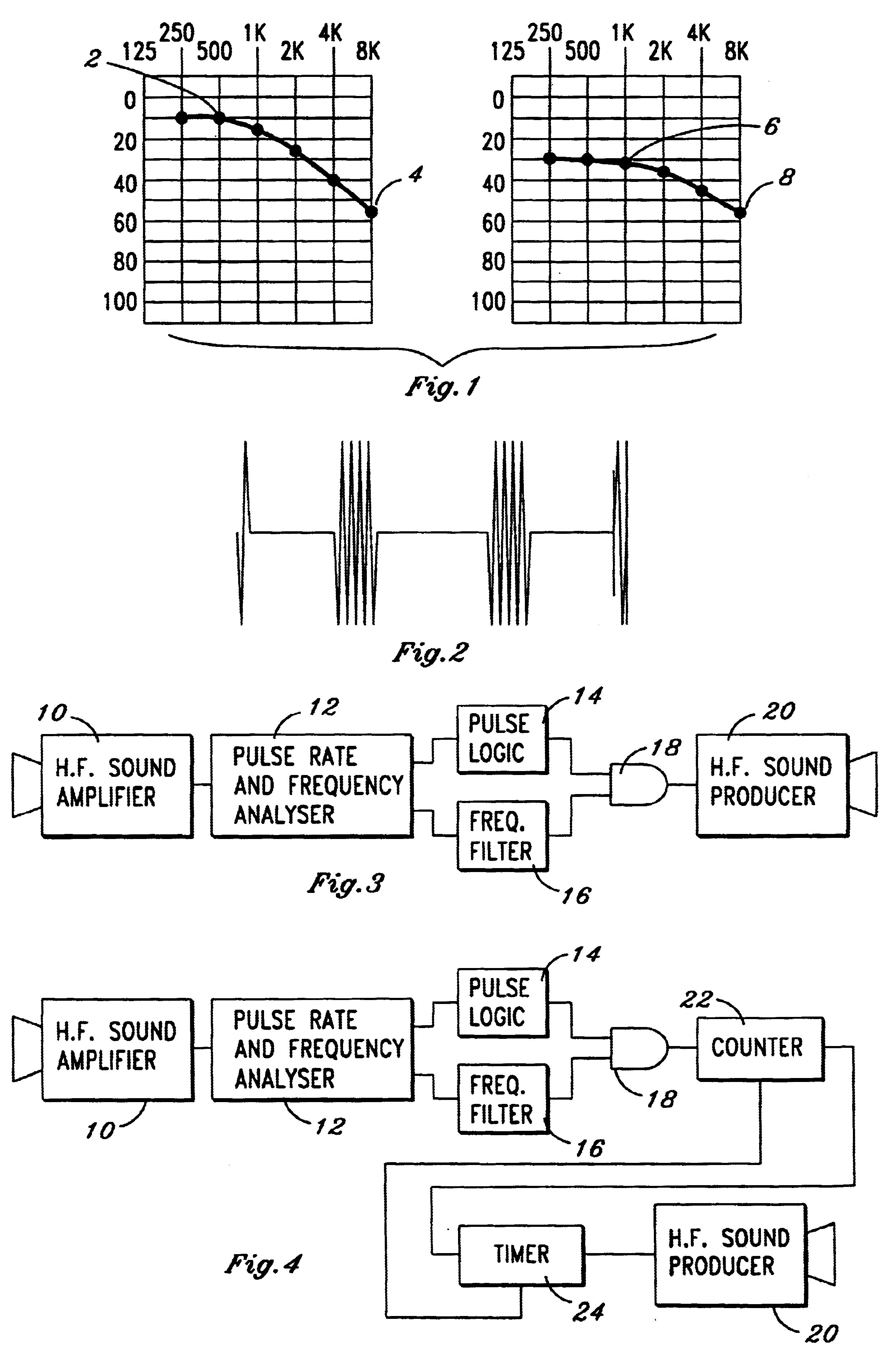
In accordance with a first embodiment of the present invention, FIG. 3 shows a simplified block diagram of a sonic relay which is adapted to receive a high frequency sound comprising sonic pulses or beeps of the type described in FIG. 2. All of the separate components pictured in the blocks are conventional and within the design knowledge of one skilled in the art. The sound signals are amplified in high frequency (H.F.) sound amplifier 10, which supplies an amplified electrical signal to pulse rate and frequency analyzer 12. There, the pulse envelope and high frequency parts are separated by filtering techniques well known to those skilled in the art and described and referenced in the aforementioned Stockham patent 5,500,902, which is incorporated herein by reference. The pulse envelope is converted to a square wave signal and fed to pulse logic block 14. Logic block 14 is designed to test the pulse repetition rate or duty cycle of the square wave and to provide output logic level...

second embodiment

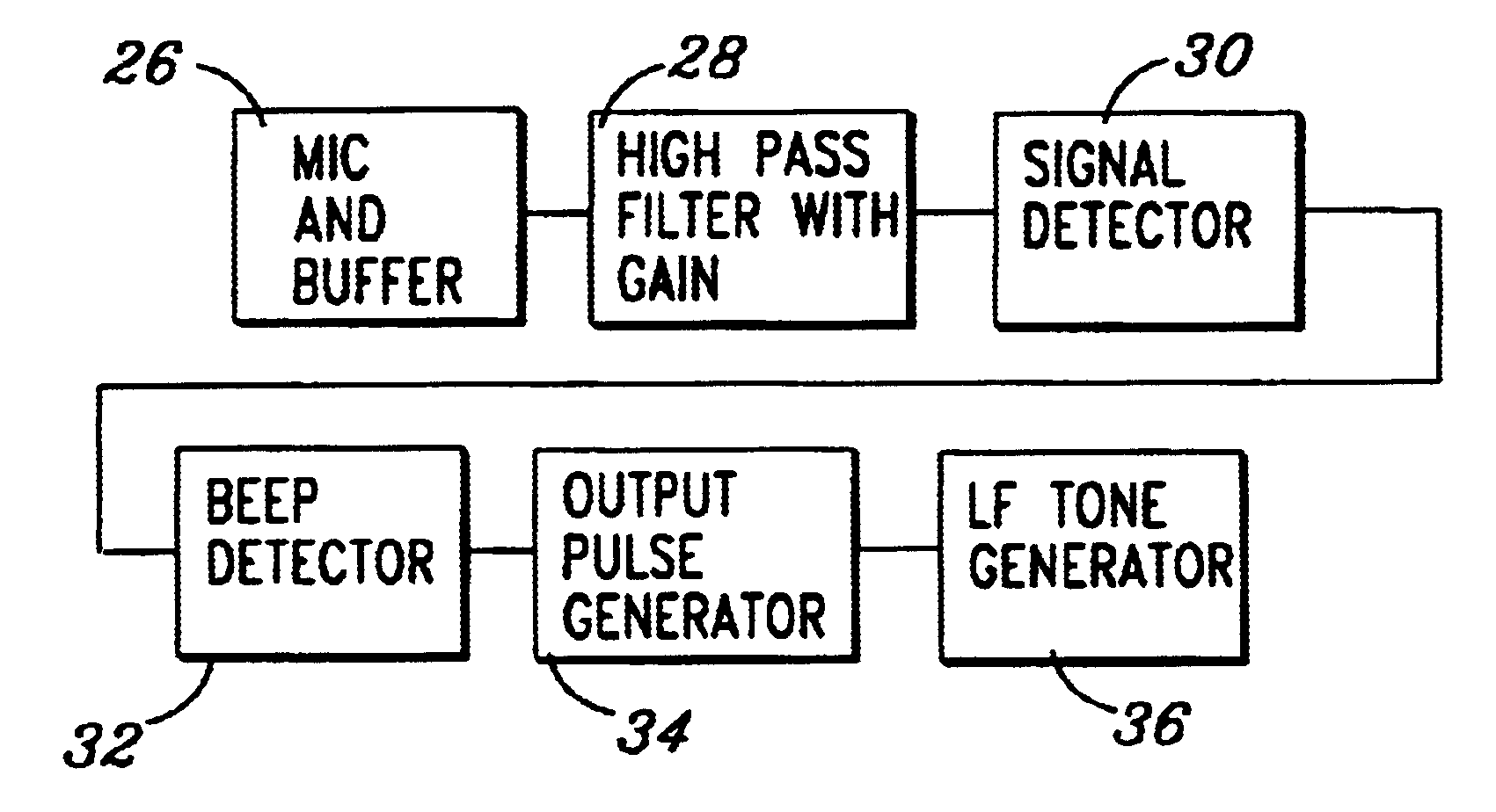
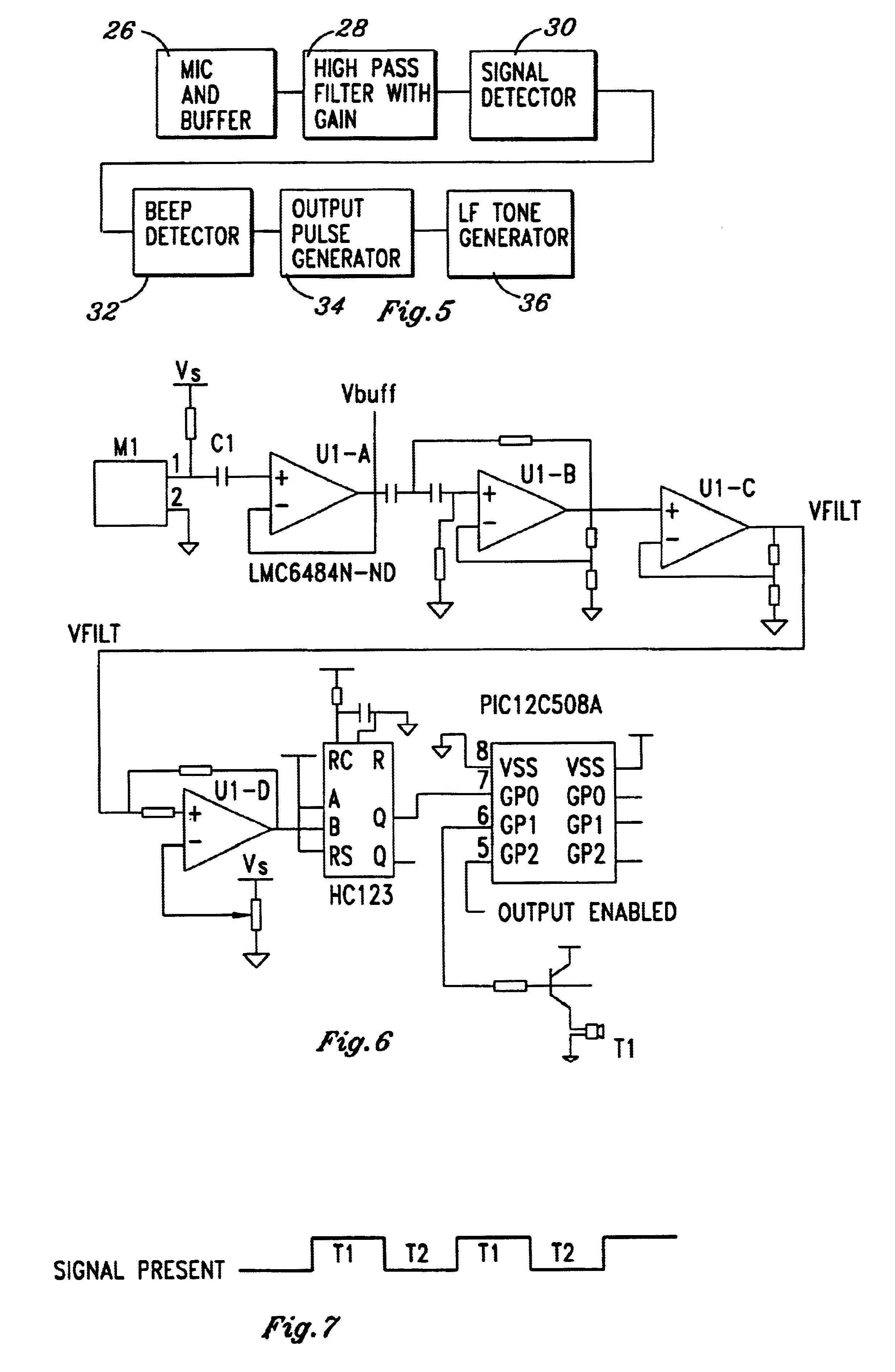
FIG. 5 is a system block diagram for a second embodiment of the invention. Rather than combining first and second logic signals in an AND circuit, the signals are processed in series to first determine if the audio input signals are high frequency sonic pulses, and then to analyse in a logic circuit whether they are beeps occuring at a constant repetition rate having the requisite periodicity. FIG. 5 shows the signal flow from audio input to audio output of the sonic relay. Audio signals are received at a microphone and buffer 26. The signals include periodically occurring sonic beeps at a frequency which is within the upper range of human hearing, but inaudible to a person with frequency impaired hearing. The buffer isolates the microphone from the circuit and adds appropriate gain. A high pass filter 28 removes low frequency components from the signals. A band pass filter may be used in lieu of high pass filter 28 to also remove extraneous very high frequency noises, such as click...


PUM


Abstract

A portable battery~powered sonic relay amplifies periodic beeping sounds from an alarm clock, smoke alarm, electronic watch or the like and analyzes the sound pulses in a logic circuit. If the sounds are periodically repeated high frequency sounds, a sound producer emits loud, low frequency sounds from a buzzer or the like, which may be heard more easily by a person with high frequency impaired hearing.

Description

This invention relates generally to sonic alarm devices and more particularly to a sonic alarm device adapted for a person with high frequency hearing impairment.DESCRIPTION OF THE PRIOR ARTA large percentage of the population, especially older people, suffer impaired hearing of sounds in the high frequency part of the normal frequency range of audible hearing. A great many electronic alarm devices and warning devices emit periodic high frequency pulses. Usually these beeping sounds are generated by piezoelectric crystals. Unfortunately, these high frequency periodic beeps cannot be heard by people with high frequency hearing loss. Examples of such devices are smoke alarms, electric alarm clocks, alarm wristwatches, and some types of telephone annunciators.Hearing devices have been disclosed in the prior art which separate the received sounds into frequency ranges and then treat the frequency bands separately. Hearing devices have primarily concentrated upon restoring a full range o...

Claims


Application Information

Patent Timeline
IPC IPC(8): G09B21/00
CPCG09B21/009
Inventor CRUTCHER, WILLIAM C.
Owner CRUTCHER WILLIAM C
Why Eureka
Eureka Blog
Learn More