Waste fluid collection container

a technology of waste fluid and collection container, which is applied in printing and other directions, can solve the problems of affecting the service life of the customer, affecting the ability of fresh ink to spread through the foam, and the inability of the waste pad to absorb ink, so as to maximize the collection potential of the collection container, prevent a mess from being created, and save time and cos

Inactive Publication Date: 2003-12-09
XEROX CORP
View PDF8 Cites 11 Cited by
  • Summary
  • Abstract
  • Description
  • Claims
  • Application Information

AI Technical Summary

Benefits of technology

There are numerous situations where one needs to collect waste fluids. For example, if waste fluids are released inside machinery, such as a copier or printer, it can be necessary to collect these fluids so that they do not damage the surrounding machinery. Also, when changing the oil in an automobile, the oil must be collected and brought to a safe disposal location. To save the time and cost associated with emptying or changing collection containers, it is desirable to maximize the collection potential of a collection container.
Ink jet printers are a specific example of machinery that produces waste fluid, e.g., ink. In addition to ejecting ink onto paper or other substrates, ink jet printers also eject ink at other times. As part of the printhead maintenance routine, many ink jet printers eject ink periodically to keep them unclogged and working. This is referred to in the art as spitting. A printer controller will position the print cartridge at a maintenance station having a spit station or spittoon and cause the printhead to eject ink into the spittoon after a print cartridge has been away from a maintenance station for a specific length of time. The printer controller does this to prevent the ink or meniscus in the little used nozzles from drying and becoming too viscous. A receptacle is used to collect this ink in order to prevent a mess from being created and to prevent damage to other components of the printer.

Problems solved by technology

However, sometimes the waste pad will stop absorbing and overflow with ink.
The water evaporates out of the ink inside the perimeter of the hole thus impeding the ability for fresh ink to spread through the foam.
This is a major concern since ink leaking out of the printer will upset the customer.

Method used


Image

  • Waste fluid collection container
  • Waste fluid collection container
  • Waste fluid collection container

Examples


Embodiment Construction

While the present invention will be described with reference to specific embodiments thereof, it will be understood that the invention is not to be limited to these embodiments. On the contrary, it is intended that the present invention cover all alternatives, modifications, and equivalents as may be included within the spirit and scope of the invention as defined by the appended claims. Other aspects and features of the present invention will become apparent as the description proceeds, wherein like reference numerals have been used throughout to designate identical elements. It is further noted that all references cited in this specification, and their references, are hereby incorporated by reference where appropriate for relevant teachings of additional or alternative details, features, and / or technical background.

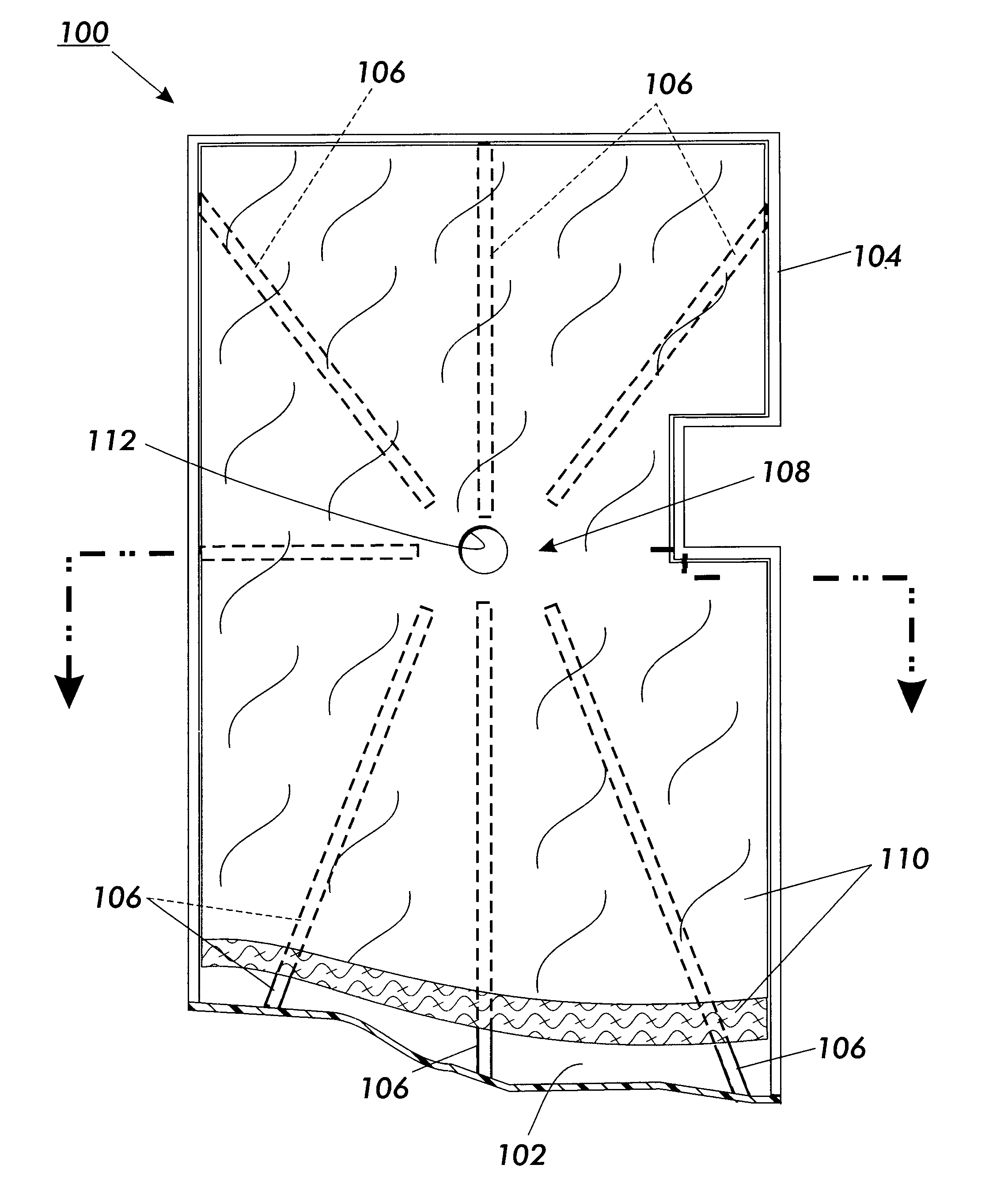
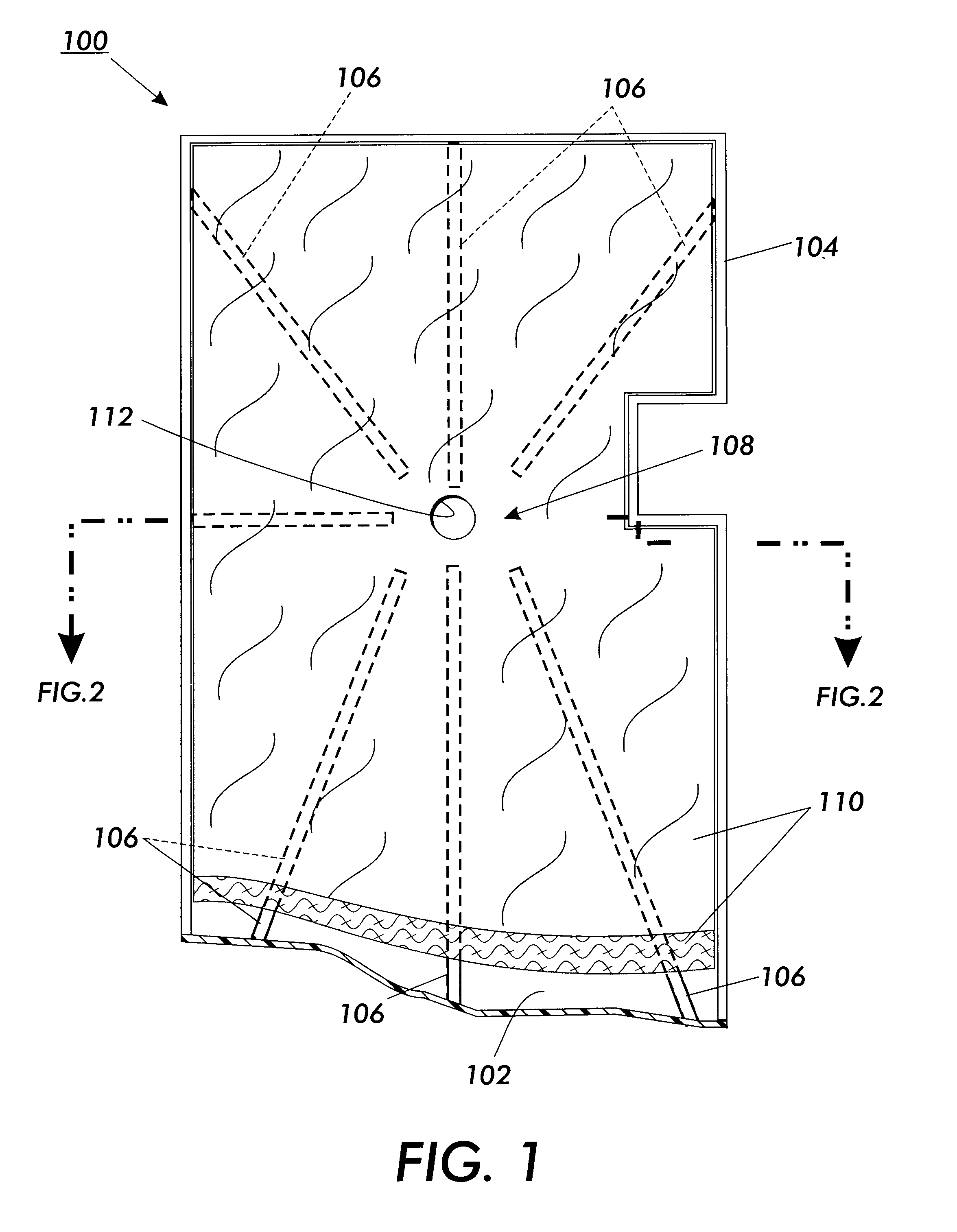
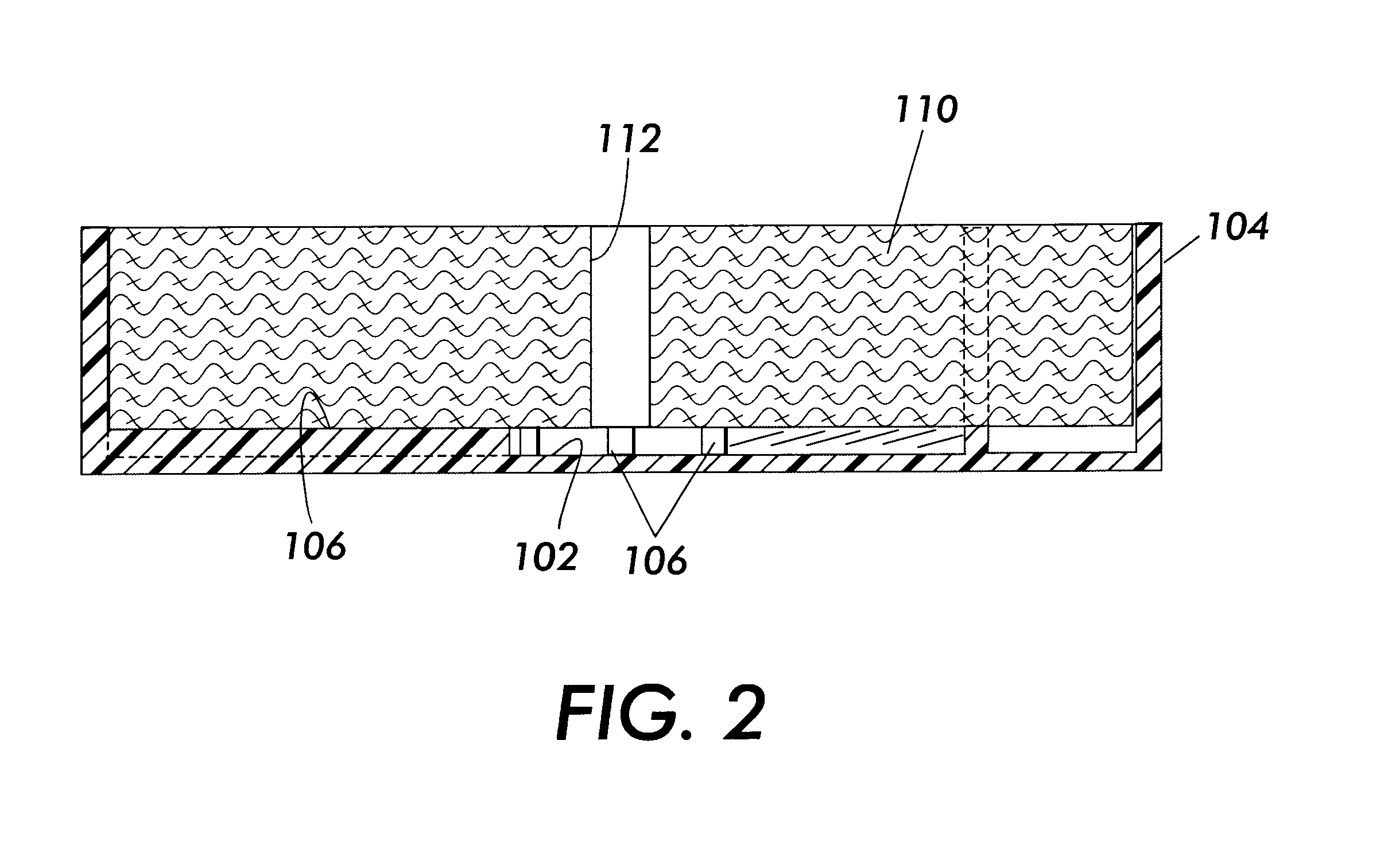
The invention is a new design for a waste fluid collection container or receptacle. One specific use of the container is for collecting waste ink in an ink jet printer....


PUM


Abstract

A waste fluid collection container, which includes a tray having a floor defined by a periphery, where the floor has a plurality of raised flow enhancing areas and a fluid absorbing member that sits inside the tray. In embodiments, the raised areas are elongated ridges extending outwardly from a central area. In other embodiments, the raised areas are a plurality of studs.

Description

BACKGROUND AND SUMMARYThe present invention relates generally to fluid ejection devices and, more particularly, to a waste fluid collection container for collecting waste fluid ejected from such a device.There are numerous situations where one needs to collect waste fluids. For example, if waste fluids are released inside machinery, such as a copier or printer, it can be necessary to collect these fluids so that they do not damage the surrounding machinery. Also, when changing the oil in an automobile, the oil must be collected and brought to a safe disposal location. To save the time and cost associated with emptying or changing collection containers, it is desirable to maximize the collection potential of a collection container.Ink jet printers are a specific example of machinery that produces waste fluid, e.g., ink. In addition to ejecting ink onto paper or other substrates, ink jet printers also eject ink at other times. As part of the printhead maintenance routine, many ink jet...

Claims


Application Information

Patent Timeline
Patent Type & Authority Patents(United States)
IPC IPC(8): B41J2/165B41J2/17
CPCB41J2/16508B41J2/1721B41J2002/1742B41J2002/1728
Inventor BERG, RICHARD H.TANNASCOLI, ROBERT J.STEVENS, DONALD M.
Owner XEROX CORP
Why Eureka
Try Eureka