Pneumatic tube distribution system and method

a technology of pneumatic tube and distribution system, which is applied in the direction of conveyors, bulk conveyors, transportation and packaging, etc., can solve the problems of increasing the cost of these large systems, merely based on equipment requirements, and significant cost of this system,

Inactive Publication Date: 2003-12-09
ADVANCED PNEUMATIC TUBES
View PDF22 Cites 39 Cited by
  • Summary
  • Abstract
  • Description
  • Claims
  • Application Information

AI Technical Summary

Problems solved by technology

As a consequence, the cost of this system, merely based on the equipment requirements, is significant.
Furthermore, the size of the hardware is relatively large and may require as much as 1,000 square feet merely to accommodate a simple six-zone system.
Since these systems are commonly used in hospitals and other expensive environments, square footage is at a premium and merely increases the cost of these large systems.
The large equipment requirements also result in high maintenance and operation costs.
The complexity of this system and the amount of time required to accomplish the various transmission steps, significantly reduces the overall throughput of the system.
A reduction in the amount of equipment required for distribution is particularly apparent in the initial cost of the distributor.

Method used


Image

  • Pneumatic tube distribution system and method
  • Pneumatic tube distribution system and method
  • Pneumatic tube distribution system and method

Examples


Embodiment Construction

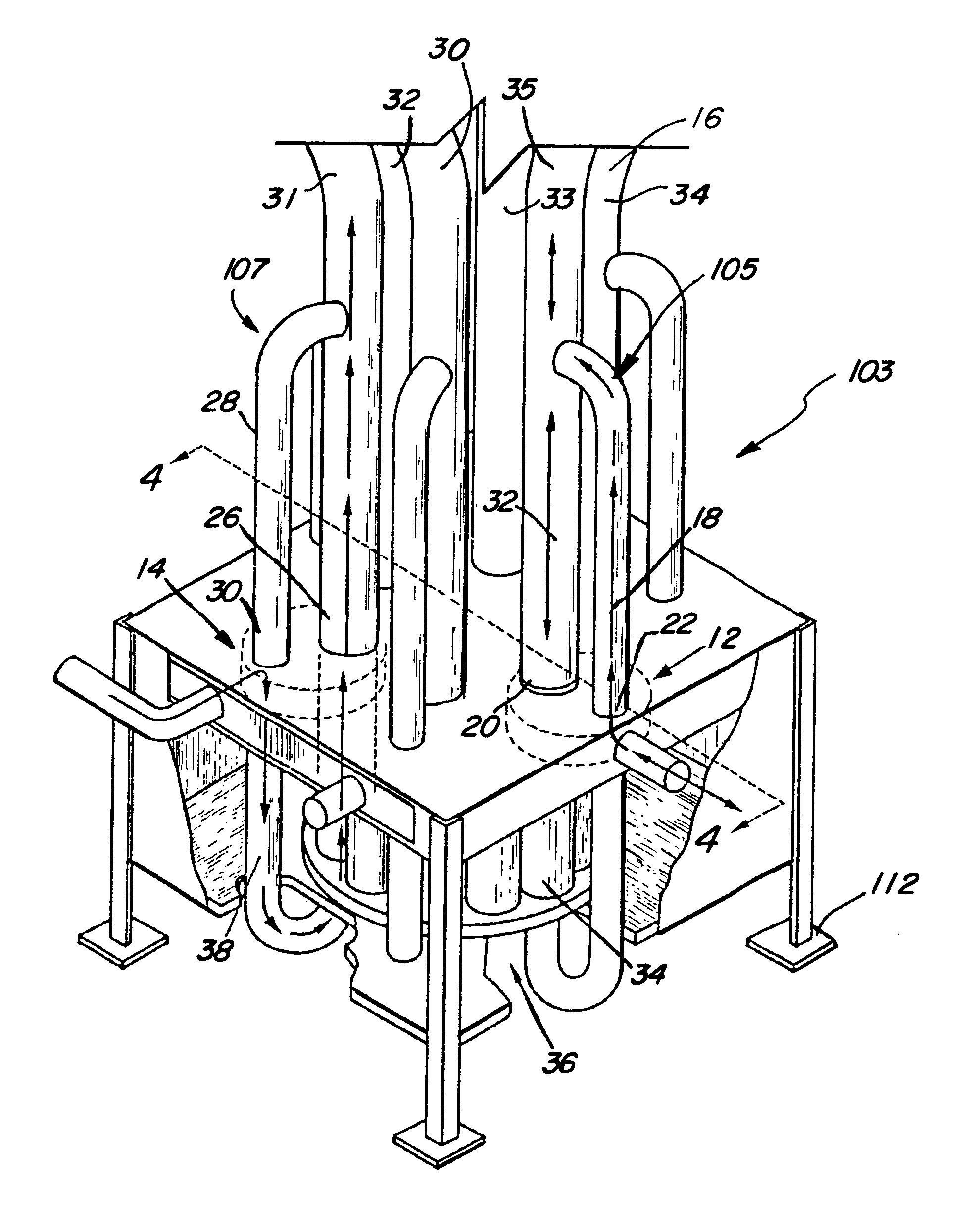
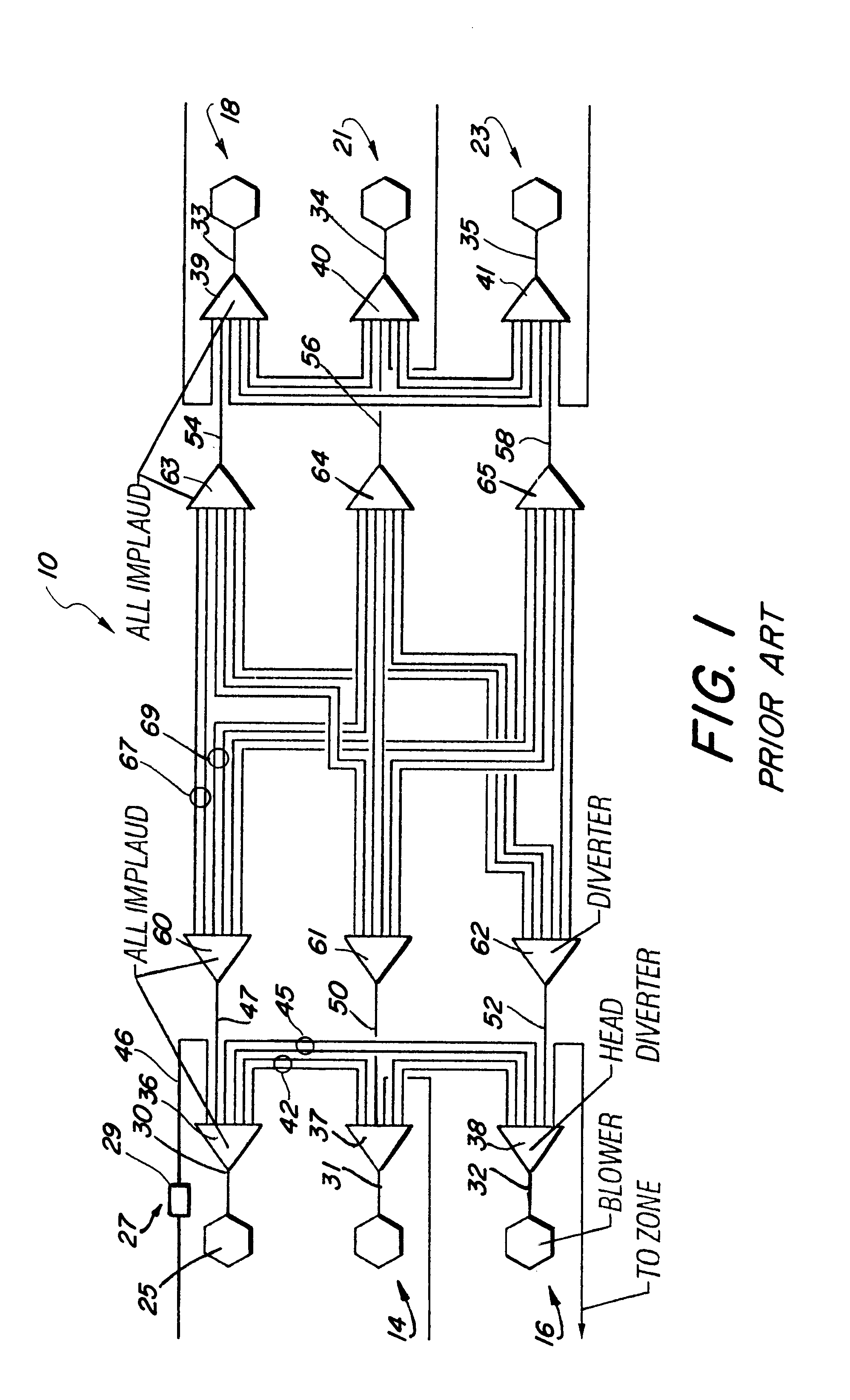
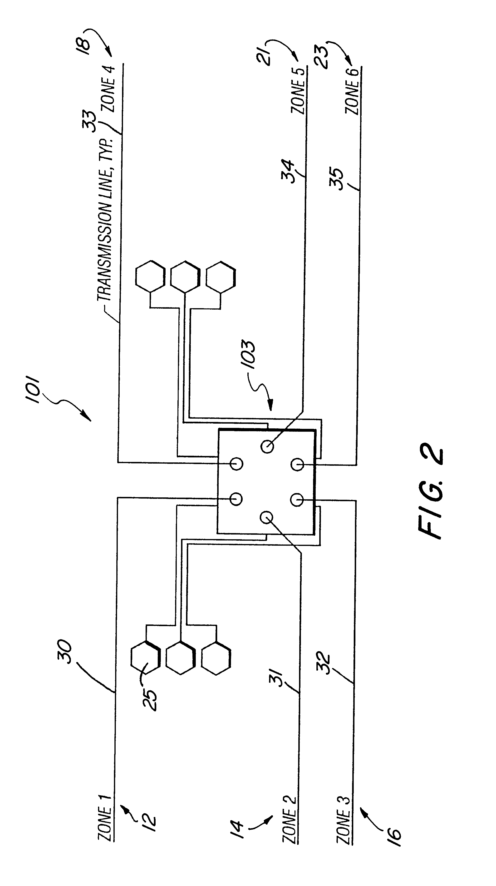
A pneumatic transport system associated with the prior art is illustrated in FIG. 1 and designated by the reference numeral 10. This system includes a multiplicity of individual stations which are combined into six individual zones shown generally by reference numerals 12, 14, 16, 18, 21 and 23. Each of the zones, such as the zone 12, includes a blower 25 which alternatively provides pneumatic pressure or vacuum at the associated zone. The blower 25 is coupled through a stopping chamber 27 where a carrier 29 can be input to or received from the system 10. The stopping chamber 27 is in turn connected to a transport tube 30 associated with the zone 12. In FIG. 1, transport tubes 31, 32, 33, 34 and 35 are illustrated for the other zones 14, 16, 18, 21, and 23, respectively.

In a typical operation, the carrier 29 is moved under pressure into the transport tube 30 which is coupled through a head diverter 36 to the remainder of the system 10. Similar head diverters 37, 38, 39, 40 and 41 ar...


PUM


Abstract

A pneumatic system for transporting a carrier includes a first transport tube coupled to a first transport station and a second transport tube coupled to a second transport station. A distributor coupled to the first transport tube and the second transport tube includes a carousel having at least one storage chamber. The carousel is rotatable about an axis to align the storage chamber with the first transport tube and the second transport tube. A source of airflow coupled to the distributor facilitates movement of the carrier through the first transport tube and into the storage chamber of the carousel, and facilitates movement of the carrier from the storage chamber of the carousel into the second transport tube. An associated method for transporting the carrier includes the step of moving the carrier from the first transport tube in a first direction into the storage chamber of the distributor. The distributor is then rotated with a carrier in the storage chamber, and the carrier is moved from the storage chamber in a second direction opposite to the first direction and into the second transport tube.

Description

1. Field of the InventionThis invention relates generally to pneumatic tube systems for transporting carriers and more specifically to those systems which transport carriers between operating zones.2. Discussion of the Relevant ArtPneumatic carrier transport systems include at least two stations where carriers can be input to the system and received from the system. In a simple system, pneumatic power provides a fluid pressure or fluid vacuum at each of the stations. This pneumatic power is applied to a tube system which interconnects the stations. In a typical operation, a carrier is inserted into the tube system at one of the stations. Pressure is applied behind the carrier or vacuum is applied in front of the carrier in order to move the carrier through a distribution tube from the initial station to the ultimate station.In more complex systems, many stations are divided into individual zones. A head diverter associated with each of the zones is in turn coupled through an associa...

Claims


Application Information

Patent Timeline
Patent Type & Authority Patents(United States)
IPC IPC(8): B65G51/34B65G51/00B65G51/32B65G51/24
CPCB65G51/24B65G51/34B65G51/32
Inventor PERKINS, JAMES D.PERKINS, DAVE MATHEWPERKINS, DOUGLAS JEFFREY
Owner ADVANCED PNEUMATIC TUBES
Why Eureka
Try Eureka