

Shoulder abduction sling
a shoulder and sling technology, applied in the field of shoulder abduction slings, can solve the problems of straps exerting a painful lateral force against the wearer's neck, sling pouches that fail to account,
- Summary
- Abstract
- Description
- Claims
- Application Information
AI Technical Summary
Benefits of technology
Problems solved by technology
Method used
Image

Examples
Embodiment Construction
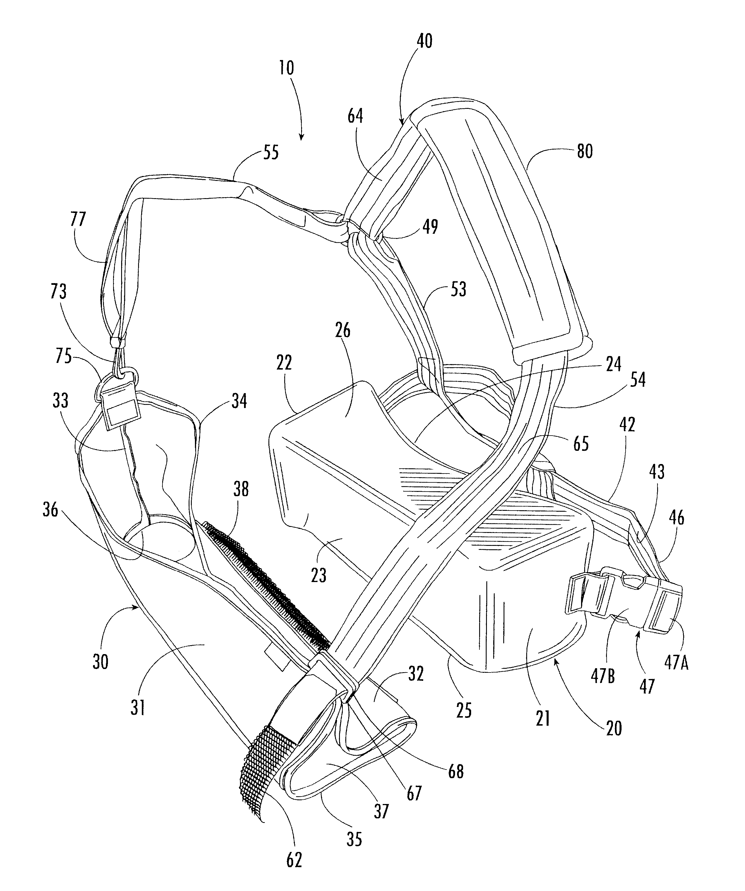
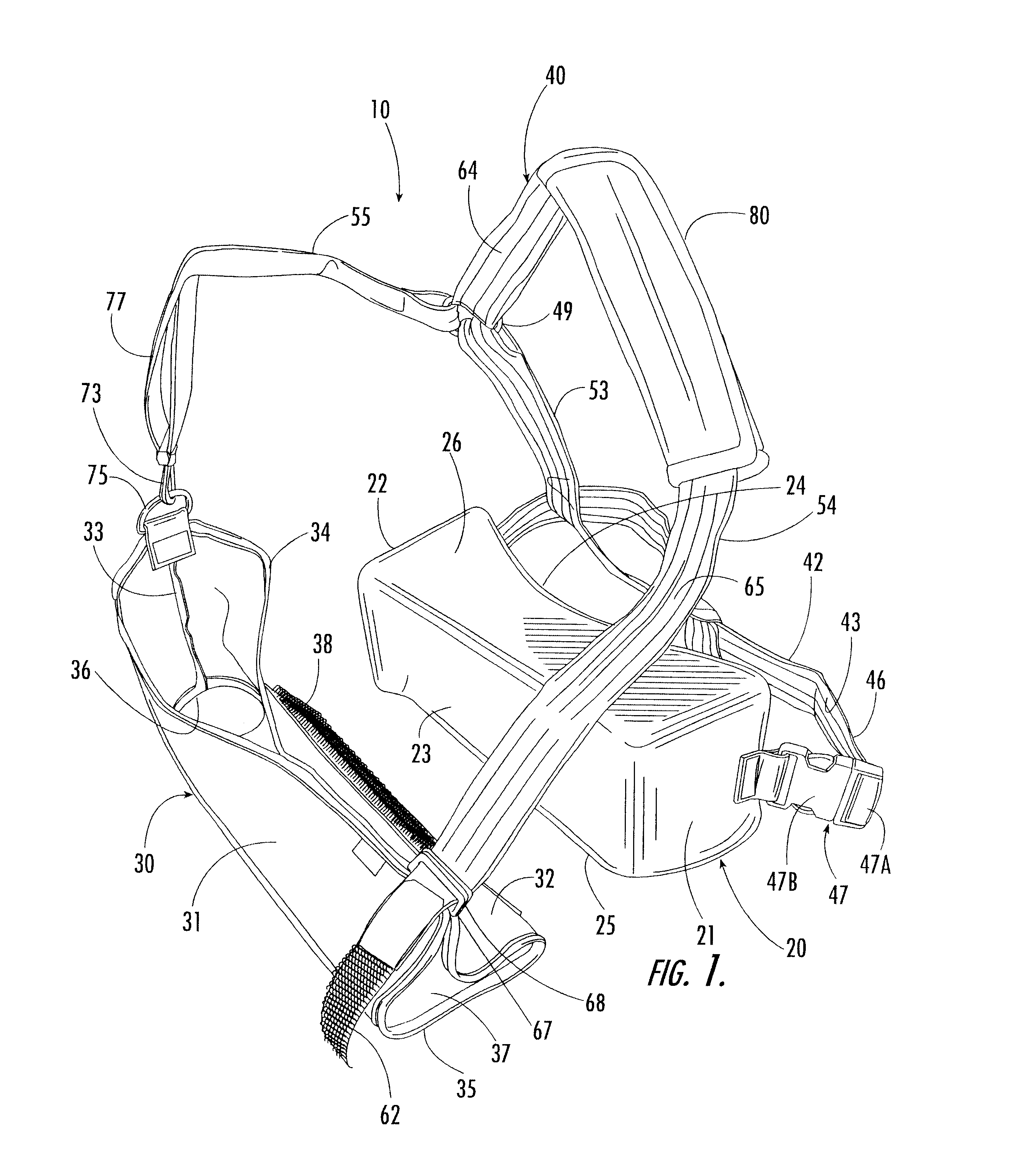
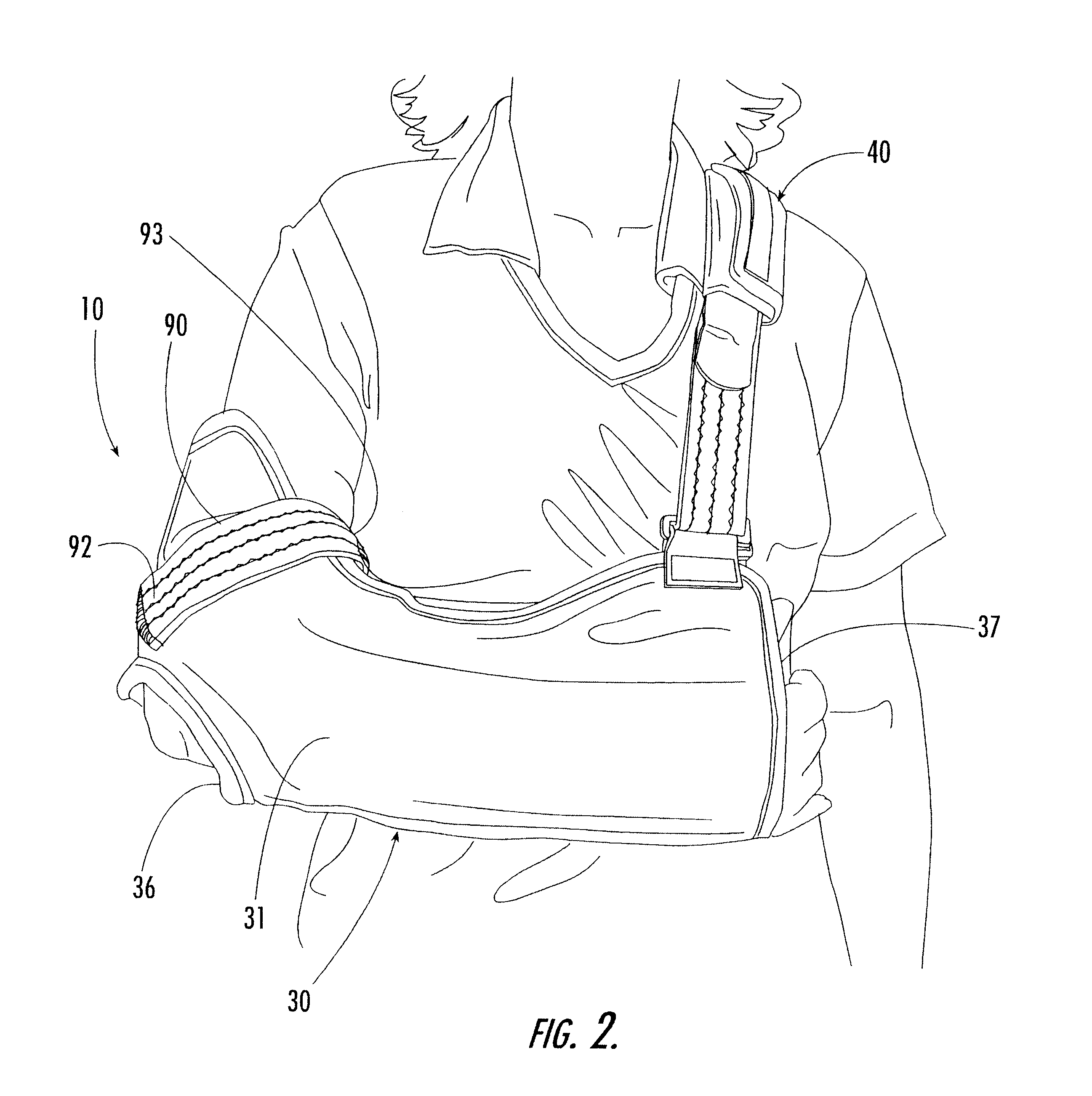
Referring now specifically to the drawings, an abduction device according to one embodiment of the present invention is illustrated in FIG. 1 and shown generally at reference numeral 10. The device 10 includes a cushion 20 that fits against a wearer's torso beneath the wearer's abducted forearm (See FIGS. 7 through 9). While the cushion 20 may be formed from any suitable materials, the cushion 20 is preferably formed from a flexible substance such as a foam material, and is covered with an elasticized or woven knitted material having a raised, fibrous surface. Furthermore, while the cushion 20 may have any suitable shape, the cushion 20 preferably has a polygonal shape and includes opposing lateral surfaces 21 and 22 that are integrally formed with anterior, posterior, inferior and superior surfaces 23, 24, 25 and 26, respectively. Lateral surface 22 is specifically contoured to accommodate and comfortably support the non-vertical angle of the humerus when the humerus is placed in a...
PUM
 Abstract
Description
Claims
Application Information