Biochar generator and associated methods

a biochar generator and generator technology, applied in the direction of vapor condensation, separation process, charging device, etc., can solve the problems of large production quantities of organic waste or biomass, typical biochar generation method, inefficient in that energy must be consumed in the collection of biomass, etc., to reduce, reduce or eliminate, reduce or eliminate

Active Publication Date: 2012-05-03
SMAIDRIS THOMAS F
View PDF10 Cites 9 Cited by
  • Summary
  • Abstract
  • Description
  • Claims
  • Application Information

AI Technical Summary

Benefits of technology

[0012]Such needs are addressed in the present invention. The biochar generator of an embodiment of the present invention provides for a biochar generator that may be carried by a vehicle, as well as associated methods which reduce, or eliminate, the need to transport biomass between a harvesting site and a storage site, as well as between the storage site and a fragmentation site. An embodiment of the present invention also advantageously provides a biochar generator to be carried by a vehicle which reduces or eliminates the need to transport fragmented biomass between the fragmentation site and the site of the pyrolysis chamber. The biochar generator and methods according to an embodiment of the present invention further advantageously reduces, or eliminates, the need to transport synthesis gasses, bio oil and biochar from the site of the pyrolysis reaction to the ultimate site of storage, consumption, refinement or application.

Problems solved by technology

It is commonly known that the cultivation and harvesting of food crops and forest products results in the production of vast quantities of organic waste or biomass.
The typical biochar generation method, therefore, is inefficient in that energy must be consumed in the collection of the biomass, in the transportation of the collected biomass to the fragmentation site, in the fragmentation of the biomass, in the transportation of the fragmented biomass to the pyrolyzing chamber, in generating the heat that drives the pyrolysis reaction, and in the transportation of the biochar, bio oil and synthesis gasses to their ultimate applications.

Method used


Image

  • Biochar generator and associated methods
  • Biochar generator and associated methods
  • Biochar generator and associated methods

Examples


Embodiment Construction

[0027]The present invention will now be described fully hereinafter with reference to the accompanying drawings, in which preferred embodiments of the invention are shown. Like numbers refer to like elements throughout. This invention may, however, be embodied in many different forms and should not be construed as limited to the embodiments set forth herein. Rather, these embodiments are provided so that this disclosure will be thorough and complete, and will fully convey the scope of the invention to those skilled in the art. Those of ordinary skill in the art will realize that the following embodiments of the present invention are only illustrative and are not intended to be limiting in any way. Other embodiments of the present invention will readily suggest themselves to such skilled persons having the benefit of this disclosure.

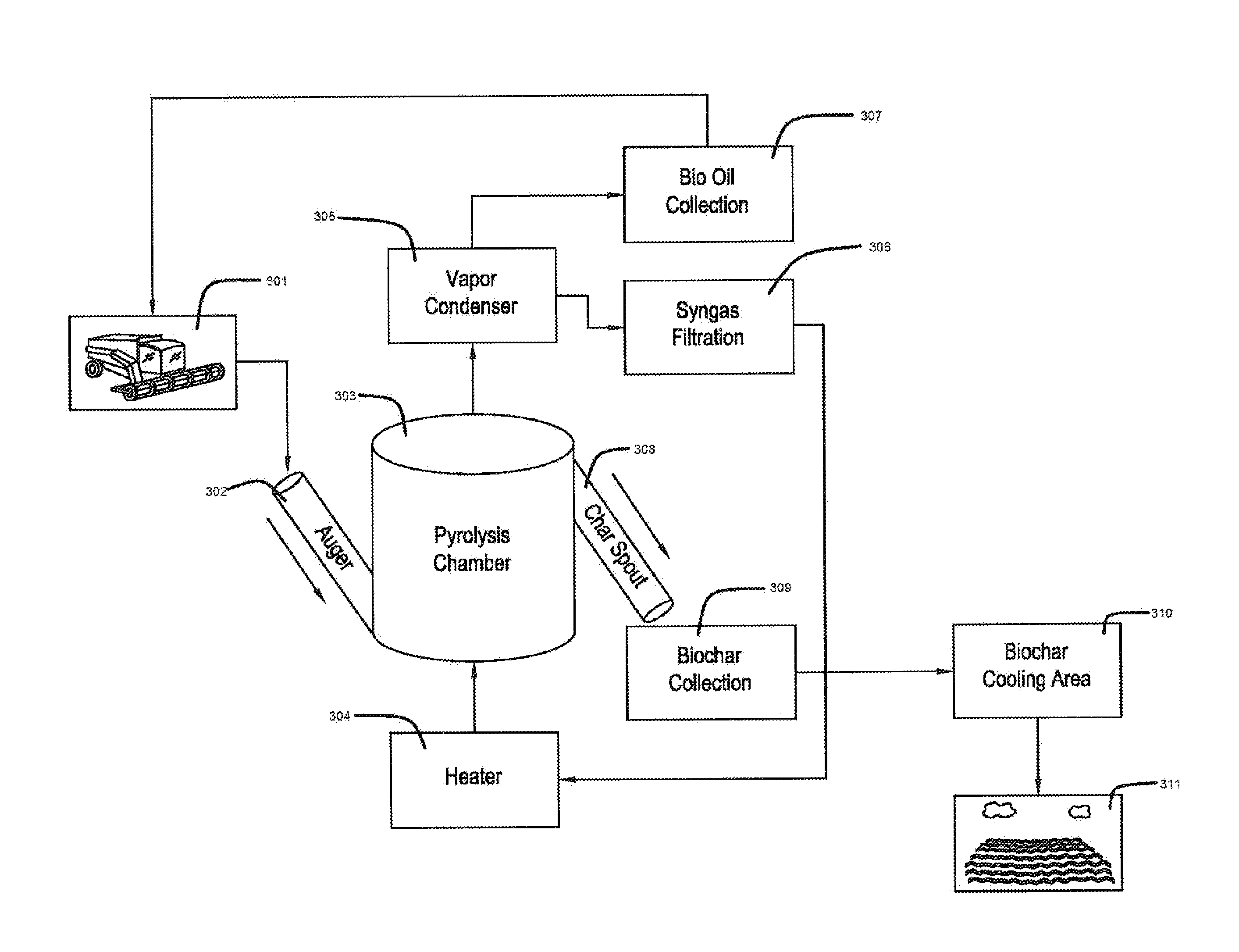
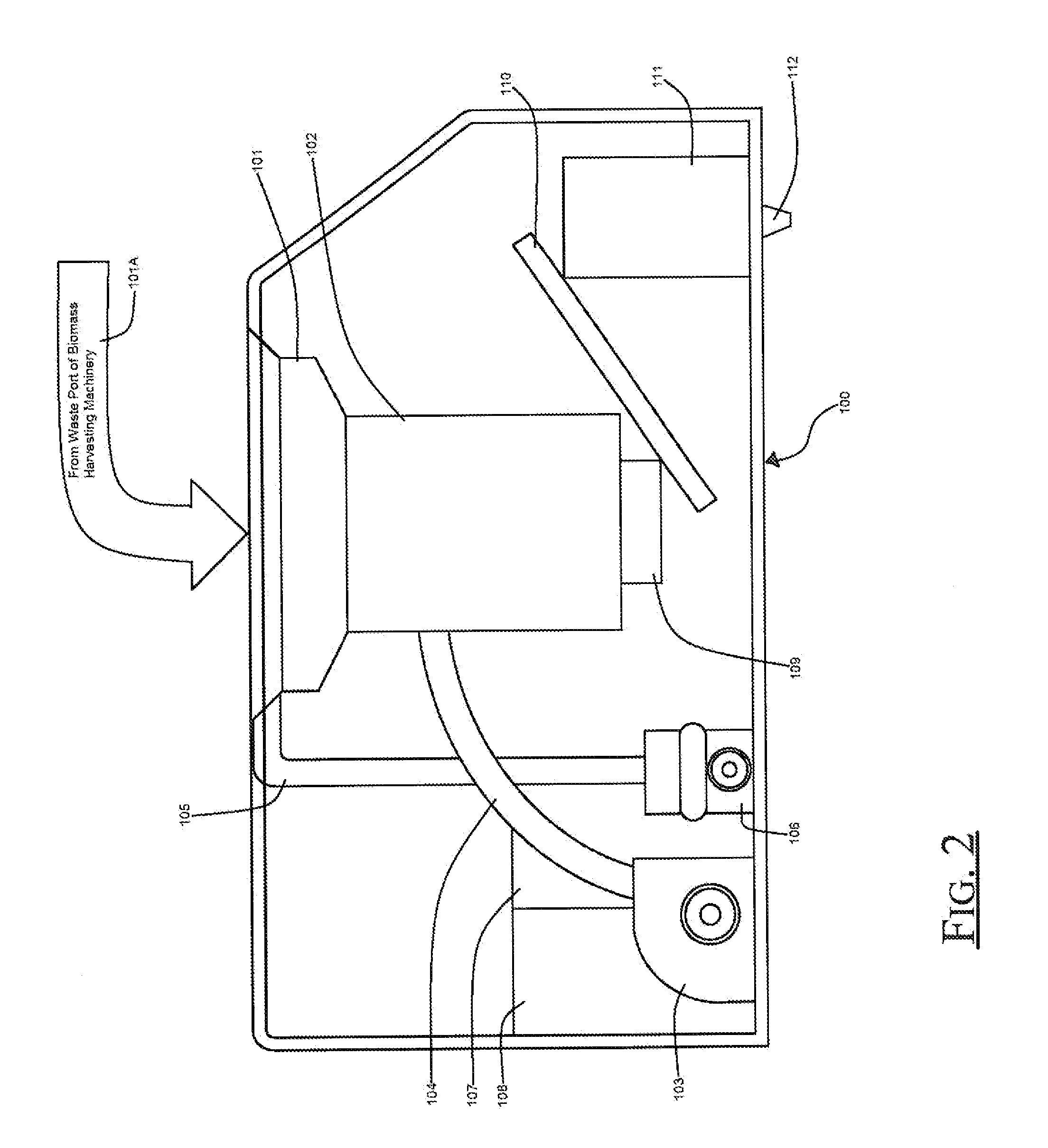
[0028]A biochar generator to be carried by a vehicle 100 according to an embodiment of the present invention can advantageously provide a system for the ...


PUM

PropertyMeasurementUnit
temperatureaaaaaaaaaa
timeaaaaaaaaaa

Abstract

A biochar generator to be carried by a vehicle may comprise a pyrolysis chamber, an auger, a heater, and a vapor condenser each connected to the pyrolysis chamber. The biochar generator may also include a synthesis gas collection chamber to collect synthesis gas, and a bio oil collection chamber to collect bio oil, each in communication with the vapor condenser. A biochar collection chamber may be included to collect biochar dispensed from the pyrolysis chamber.

Description

RELATED APPLICATIONS[0001]The present application claims the benefit of U.S. Provisional Patent Application Ser. No. 61 / 407,079 titled PORTABLE BIOCHAR GENERATOR AND ASSOCIATED METHODS filed by the inventor of the present invention on Oct. 27, 2010, the entire contents of which are incorporated herein by reference.FIELD OF THE INVENTION[0002]The present invention relates to the field of biochar generators and, more specifically, to the field of biochar generators to be carried by a vehicle to produce biochar.BACKGROUND OF THE INVENTION[0003]It is commonly known that the cultivation and harvesting of food crops and forest products results in the production of vast quantities of organic waste or biomass. It is also commonly known that biomass may be decomposed at high temperatures and in a reduced-oxygen setting in a reaction known as pyrolysis. Pyrolysis results in the release of volatile gasses and a residual solid material known as biochar. When the volatile gasses are condensed, a...

Claims


Application Information

Patent Timeline
Patent Type & Authority Applications(United States)
IPC IPC(8): C10B53/00C10B57/00
CPCA01D43/00Y02E50/14C10C5/00C10B53/02Y02E50/10
Inventor SMAIDRIS, THOMAS F.
Owner SMAIDRIS THOMAS F
Why Eureka
Try Eureka