Prosthetic aortic valve

a prosthetic and aortic valve technology, applied in the field of prosthetic aortic valves, can solve the problems of high risk of thromboembolism, high cost and inconvenience, and impair health, and achieve the effect of minimizing or eliminating the additional risk of infection and/or thromboembolism

Inactive Publication Date: 2005-10-04
DILLING EMERY W
View PDF14 Cites 158 Cited by
  • Summary
  • Abstract
  • Description
  • Claims
  • Application Information

AI Technical Summary

Benefits of technology

[0027]Normally, shielded fibrous inserts would be used, if needed, on tissue-contact surfaces of semirigid flanges because of the added mechanical strength they can confer on the sutured connection between a flange and a patient's tissue. Regardless of how (or whether) shielded fibrous inserts are used on valves of the p

Problems solved by technology

Still, a continued high risk of thromboembolism from the mechanical valves mandates lifelong anticoagulant therapy for patients receiving them.
This therapy is costly and inconvenient, and it predisposes patients to a variety of complications that can impair health and shorten life (e.g., stroke arising from either excessive or insufficient anticoagulation).
But one major structural feature found on almost all modern prosthetic mechanical valves continues to cause significant morbidity and mortality.
The resulting sutures, while tedious and time-consuming to place in large numbers, provide needed strength to retain the implanted valve in place and to avoid blood leakage by ensuring a good cuff-to-annulus seal.
While they were initially described as improvements, the valves of the '742 and '550 patents have achieved only limited acceptance.
In part, this is because pre-existing disease states (e.g., calcification of the annulus) and a limited range of valve sizes make it difficult in practice to achieve a close and mechanically strong implant attachment to an annulus that has a non-uniform sealing surface

Method used


Image

  • Prosthetic aortic valve
  • Prosthetic aortic valve
  • Prosthetic aortic valve

Examples


Embodiment Construction

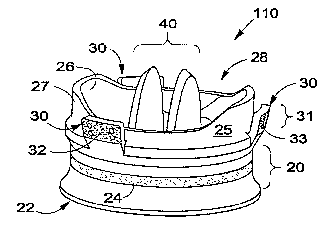
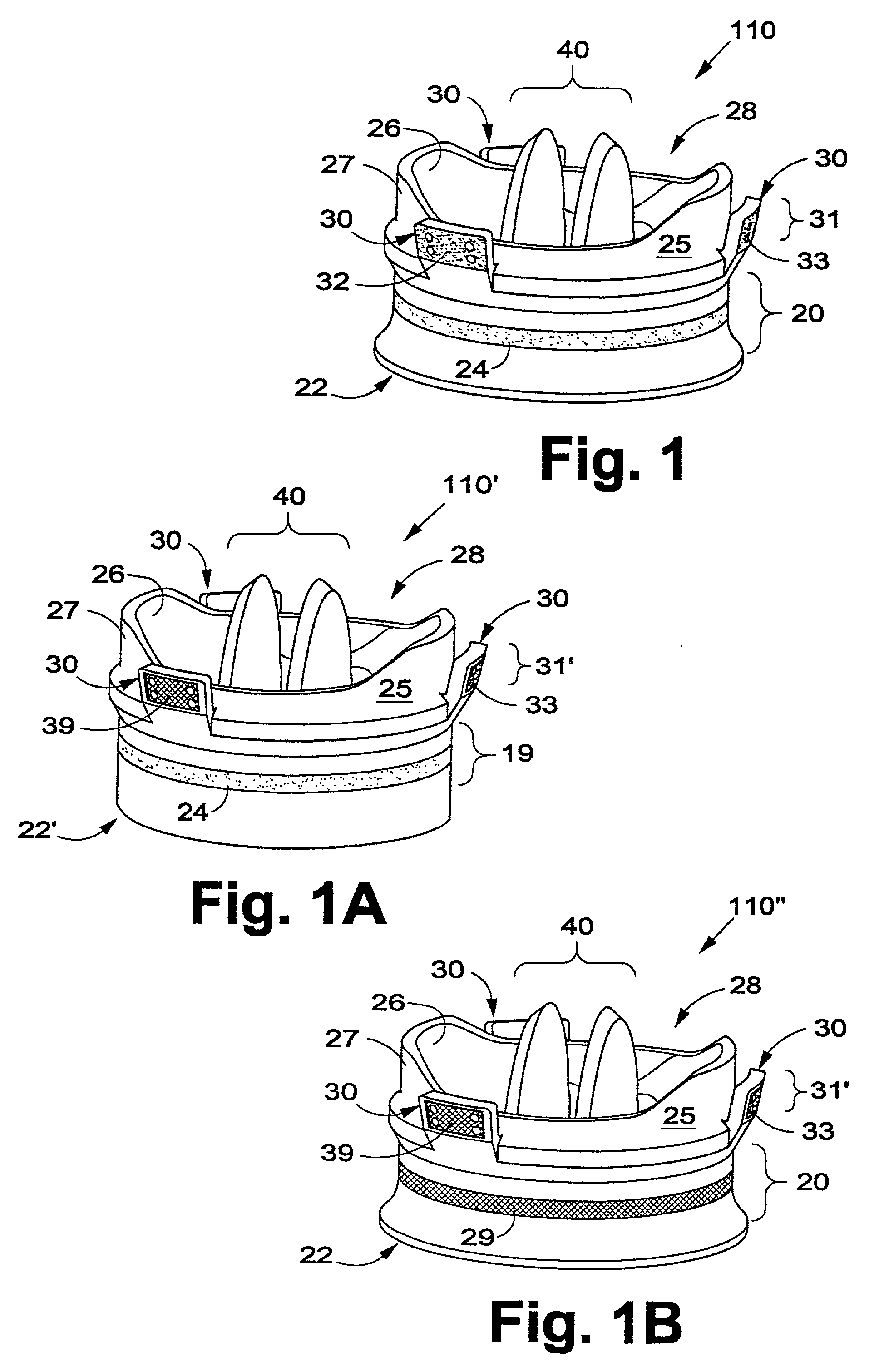
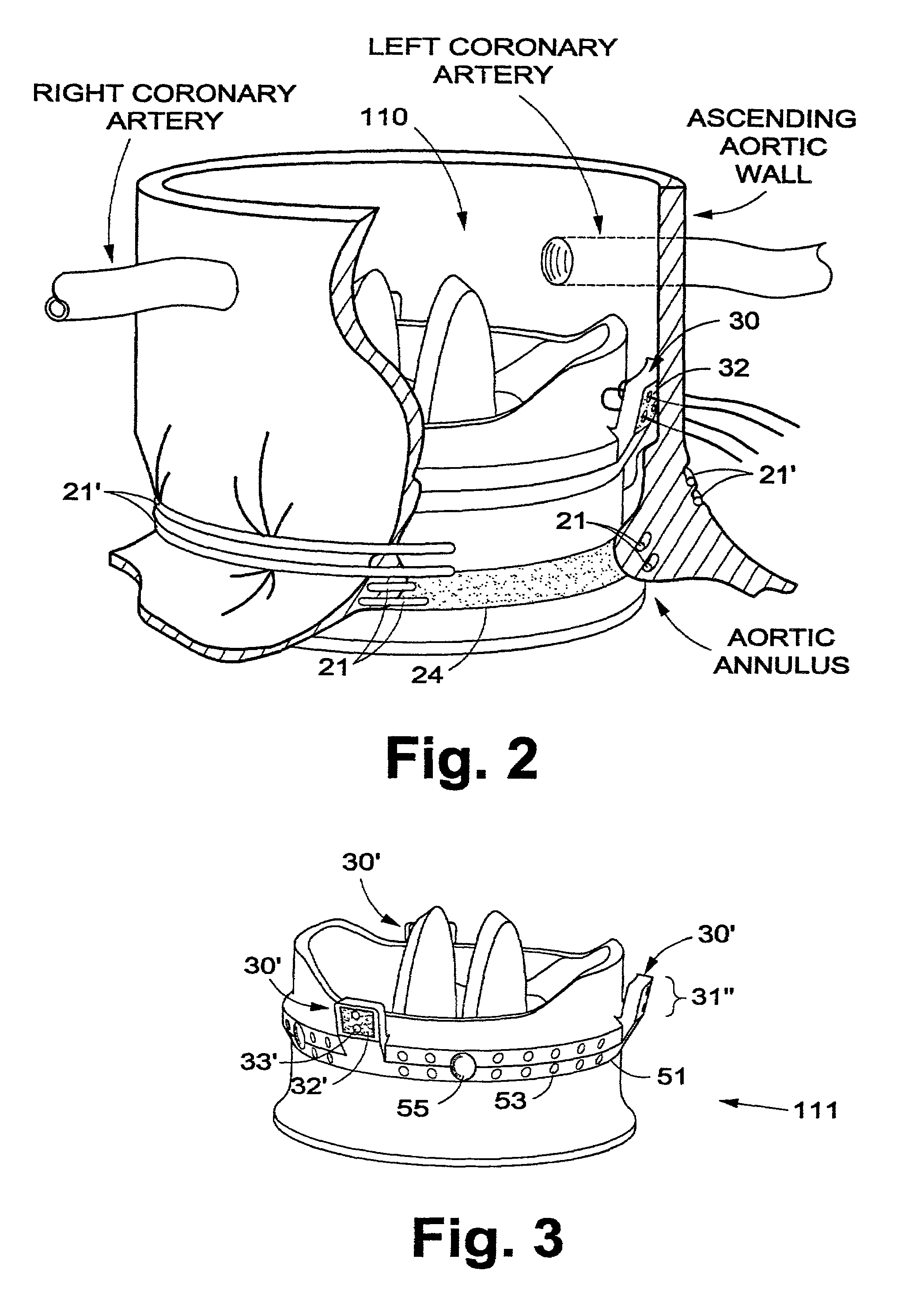
[0048]A semirigid sewing flange of the present invention allows placement of a plurality of interrupted sutures for securing a prosthetic valve to the aortic valve commissures and / or to the ascending aortic wall between the commissures. Since the commissures themselves are generally not evenly spaced around the annulus, the interrupted sutures are generally not evenly spaced either. Thus, while suitable for the valve securing function, these interrupted sutures are not preferred for the function of sealing to prevent blood leakage around an implanted prosthetic valve.

[0049]The function of sealing to prevent blood leakage around implanted valves of the present invention is provided by tension in one or more circumferential tensioning cords. Each such tensioning cord is placed within the tissue surrounding a patient's aortic annular opening (as, for example, by one or more purse-string sutures placed within the tissue) and / or around the ascending aortic wall distal to the aortic annul...


PUM


Abstract

A prosthetic aortic valve is designed to be implanted in the natural aortic annulus and to extend into the ascending aorta to a point short of the right and left coronary arteries. Blood leakage around the valve is prevented by tension in one or more circumferential cords drawing annular tissue into sealing contact with an external sealing ring on the valve body. The security of the valve's attachment to a patient is assured with a plurality of interrupted sutures between a semirigid flange on the valve outer surface and the patient's aortic commissures and/or the patient's ascending aortic wall. The sutures are preferably attached to posts or cleats on the semirigid sewing flange, the flange being spaced apart from the valve inlet by the sealing ring.

Description

BACKGROUND[0001]The present invention relates to surgically implantable mechanical valves that can replace cardiac valves damaged by disease or injury. In particular, the invention comprises methods and apparatus for total replacement of aortic valves.[0002]Mechanical prosthetic aortic valves are typically attached to the tissue of the natural valve annulus and simulate the function of aortic valve semilunar leaflets, ensuring one-way arterial blood flow out of the left ventricle of the heart. They have been in clinical use for about 50 years, and during that time prosthetic valves' durability and hemodynamic characteristics have been improved significantly. Still, a continued high risk of thromboembolism from the mechanical valves mandates lifelong anticoagulant therapy for patients receiving them. This therapy is costly and inconvenient, and it predisposes patients to a variety of complications that can impair health and shorten life (e.g., stroke arising from either excessive or ...

Claims


Application Information

Patent Timeline
IPC IPC(8): A61F2/06A61F2/24
CPCA61F2/2403A61F2/2409
Inventor DILLING, EMERY W.
Owner DILLING EMERY W
Why Eureka
Try Eureka