Back-supported load-carrying mechanism with suspension-mounted pivoting lumbar support

a technology of lumbar support and back support, which is applied in the direction of beach chairs, travelling objects, chairs, etc., can solve the problems of not conforming the backs of the wide variety of individuals wearing the backpack device, the comfort and functionality of the existing lumbar support,

Inactive Publication Date: 2003-12-16
PRP +1
View PDF29 Cites 23 Cited by
  • Summary
  • Abstract
  • Description
  • Claims
  • Application Information

AI Technical Summary

Benefits of technology

Accordingly, it is an object of the present invention to provide a new and improved back-supported load-carrying mechanism which includes a suspension-mounted pivoting lumbar support element to allow for an even distribution of cargo weight to the lower back of a user, and to provide a shock-absorbing mechanism, thus eliminating stress to the neck and back areas of the user.

Problems solved by technology

However, there are problems with the comfort and functionality of these existing lumbar supports.
Due to the shortcomings of existing lumbar supports, backpack devices often slide down from the weight of the load being carried and tend to shift off center providing uneven weight distribution on the shoulders and back of the user.
Further, existing lumbar supports do not conform to the backs of the wide variety of individuals wearing the backpack device.

Method used


Image

  • Back-supported load-carrying mechanism with suspension-mounted pivoting lumbar support
  • Back-supported load-carrying mechanism with suspension-mounted pivoting lumbar support
  • Back-supported load-carrying mechanism with suspension-mounted pivoting lumbar support

Examples


first embodiment

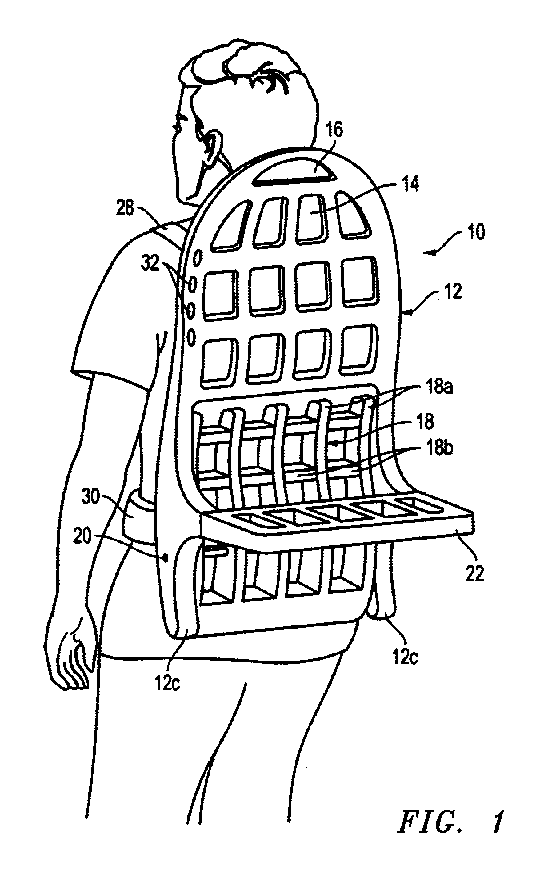
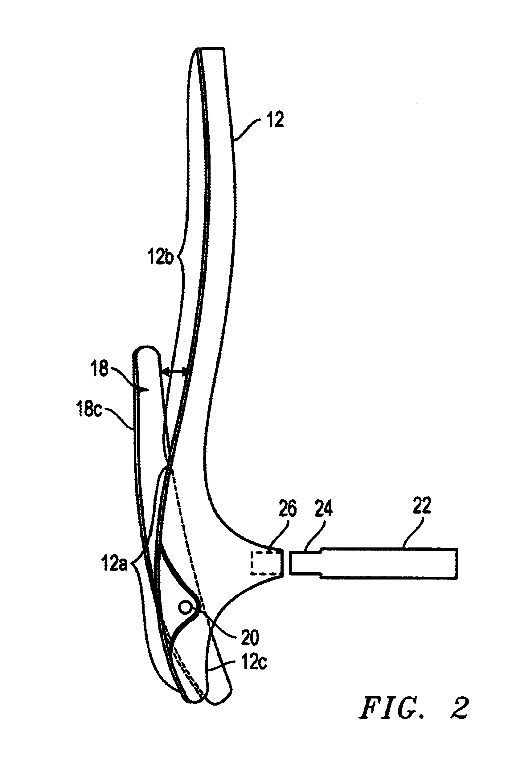
FIG. 1 is a rear perspective view of the present invention in its folded configuration. The back-supported load-carrying mechanism 10 includes a molded frame 12. The front side of the frame (the side resting against the user's back) is designed to mimic the curvature of the spine. The front side of the frame has a region of convex curvature 12a (see FIG. 2) throughout the thoracic, lumbar, and upper sacrum areas of the back. The frame transitions to a region of concave curvature 12b just above the thoracic region towards the upper back, and neck areas.

The frame 12 has a raised lip edge around all the forward facing surfaces for accepting, containing, and / or protecting the edges of a polyolefin foam inlay. This foam is applied to all surfaces of the back-supported load-carrying mechanism which come in direct contact with the user's body. This includes the molded back-support portion of the frame, the rear and front surfaces of the lumbar support element 18 and both integrated vertica...

second embodiment

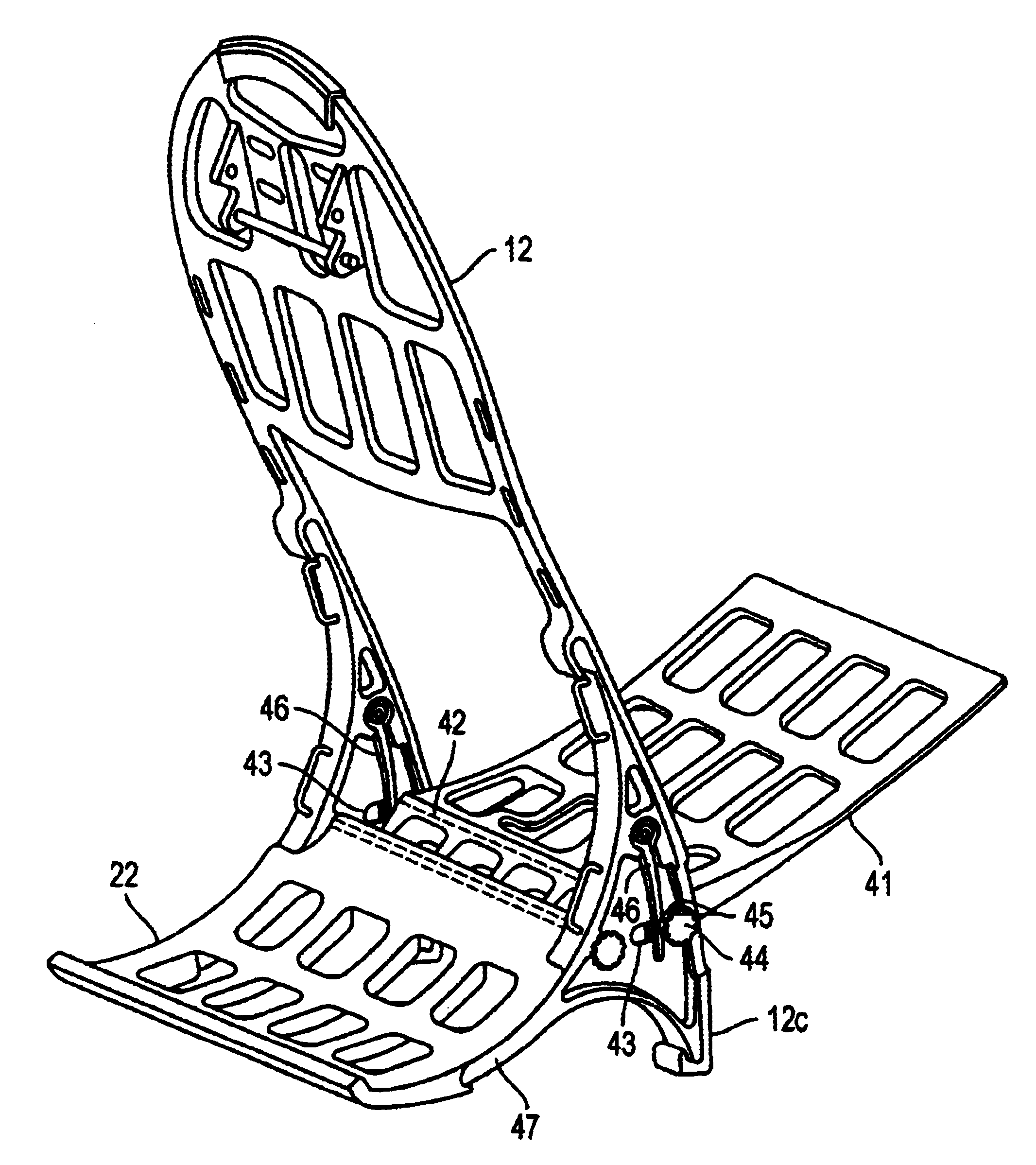
Another change in the second embodiment is that the load support element 22 attaches to the frame 12 in a different manner. The load support element slides onto two rear leg extensions 47 on each side of the frame. A second horizontal shaft 48 extends through the forward portion of the load support element, and extends through each of the vertical frame extensions 12c. A second fastener 49 is attached to each end of the second horizontal shaft to retain the shaft in place. To remove the load support piece, one of the second fasteners is removed, and the second horizontal shaft is pulled out of the load support piece. The load support piece is then slid off of the rear leg extensions 47. The second horizontal shaft may then be replaced in the frame to function as a stop for the back end of the pivoting lumbar support when it is rotated to the seat position.


PUM


Abstract

A back-supported load-carrying mechanism that includes a rigid frame having a lower portion that includes an opening between a first vertical side and a second vertical side. A horizontal shaft is mounted to the sides and extends through the opening. A lumbar support element is pivotally mounted on the horizontal shaft. The horizontal shaft is mounted to the vertical sides of the frame with a suspension mechanism that enables each end of the horizontal shaft (and each side of the lumbar support element) to move fore and aft in relation to the frame. Tensioners mounted on the frame apply forward pressure to the shaft. Two rear leg extensions on each side of the frame enable the load-carrying mechanism to stand upright when placed on the ground. The lumbar support can pivot approximately 95 degrees to a position enabling the load-carrying mechanism to be utilized as a chair.

Description

1. Technical Field of the InventionThe present invention relates to a back-supported load-carrying mechanism and, in particular, to a back-supported load-carrying mechanism that includes a suspension-mounted, pivoting lumbar support element.2. Description of Related ArtThe use of backpack devices (backpacks and backpack frames used for carrying loads) is known in the prior art. Existing embodiments have utilized a single horizontal bar, a padded horizontal bar, a narrow strap, or molded pads to provide support for the backpack device in the lumbar region of the user's back. However, there are problems with the comfort and functionality of these existing lumbar supports. Due to the shortcomings of existing lumbar supports, backpack devices often slide down from the weight of the load being carried and tend to shift off center providing uneven weight distribution on the shoulders and back of the user. Further, existing lumbar supports do not conform to the backs of the wide variety of...

Claims


Application Information

Patent Timeline
Patent Type & Authority Patents(United States)
IPC IPC(8): A45F3/00A45F4/02A47C9/10A47C9/00A45F3/10A45F4/00A47C1/14A47C1/00A45F3/02
CPCA45F3/10A45F4/02A47C1/146A45F2003/125A45F2003/025
Inventor MCUMBER, ANDREW
Owner PRP
Why Eureka
Try Eureka